5-2 Extension cable wire bound specifications
5-3
Extension cable wire bound specifications
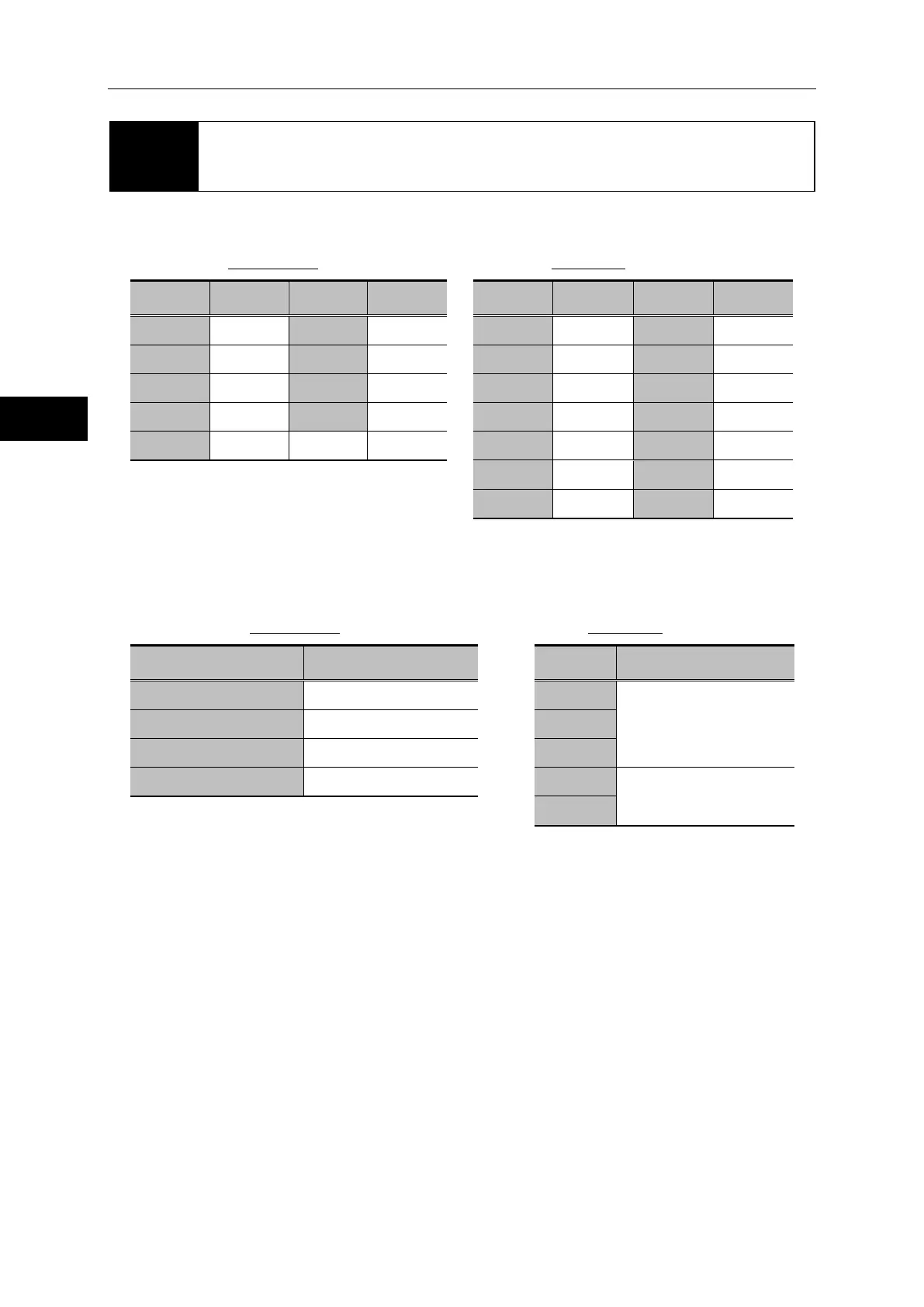
The following tables show the wire bound specifications of the relay cables.
(1) For encoders (EWA-E××-JST09-3M14)
Actuator side Driver side
Pin NO.
Pin NO.
Pin NO.
Pin NO.
1 A phase 6 W phase
1 +5V 8 GND
2 B phase 7 +5V
2 B+ phase 9 U+ phase
3 Z phase 8 GND
3 Z+ phase 10 U- phase
4 U phase 9 N.C.
4 B- phase 11 V+ phase
5 V phase
5 A+ phase 12 V- phase
Connector: SM09B-NSHSS-TB
J.S.T. Mfg. Co., Ltd.
6 Z- phase 13 W+ phase
7 A- phase 14 W- phase
Cover: 10314-52F0-008
(2) For motors (EWA-M××-JST04-TN2)
Actuator side Driver side
Pin NO. Signal name
Connector
1 U phase
U phase
XW4B-06B1-H1
Omron
2 V phase
V phase
3 W phase
W phase
4 FG
FG
Round crimp-style
terminal 1.25-4
With insulating coating
Housing: PARP-04V
Retainer: PMS-04V-S
Contact: S(B)PA-001T-P0.5
Shield
J.S.T. Mfg Co.,Ltd
 Loading...