EasyManuals Logo

Harmonic Drive RSF supermini Series User Manual

Harmonic Drive RSF supermini Series
65 pages
To Next Page IconTo Next Page
To Previous Page IconTo Previous Page
Page #27 background imageLoading...
Page #27 background image
1-16 Cable specifications
1-17
1
2
3
4
5
6
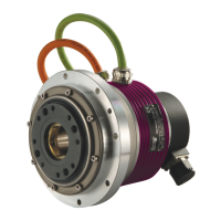
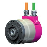
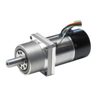
Overview of the RSF supermini series
1-16 Cable specifications
The following tables show specifications of motor lead wires, brake lead wires and encoder lead wires
of the RSF supermini actuators.
Motor cable
Pin No.
Color
Signal name
Remark
1
Red
(RED)
U
Motor phase-U
2
White
(WHT)
V
Motor phase-V
3
Black
(BLK)
W
Motor phase-W
4
Green
1
(GRN)
FG
Grounding *RSF-5B only
1: Green/yellow tubes are attached in the vicinity of the connector.
Manufactured by J.S.T. Mfg Co., Ltd
Brake lead wire
Pin No.
Line color
1
Blue
(BLU)
2
Yellow
(YEL)
3
Gray
(GRY)
Manufactured by J.S.T. Mfg Co., Ltd
Encoder lead wire
Pin No.
Color
Signal name
Remark
1
White
(WHT)
A
A phase output
2
Green
(GRN)
B
B phase output
3
Yellow
(YEL)
Z
Z phase output
4
Brown
(BRW)
U
U phase output
5
Blue
(BLU)
V
V phase output
6
Orange
(ORG)
W
W phase output
7
Red
(RED)
+5V
Power supply input
8
Black
(BLK)
GND
Power supply input
9
Connector used
Housing:
NSHR-09V-S
Terminal:
SSHL-003T-P0.2
Manufactured by J.S.T. Mfg Co., Ltd
Connector used
Housing:
PALR-04VF (with retainer)
Contact:
S(B)PAL-001T-P0.5
Recommended connector
Housing:
PARP-04V (with retainer)
Contact:
S(B)PA-001T-P0.5
Connector used
Housing:
PALR-03VF (with retainer)
Contact:
S(B)PAL-001T-P0.5
Recommended connector
Housing:
PARP-03V (with retainer)
Contact:
S(B)PA-001T-P0.5

Questions and Answers:

Question and Answer IconNeed help?

Do you have a question about the Harmonic Drive RSF supermini Series and is the answer not in the manual?

Harmonic Drive RSF supermini Series Specifications

General IconGeneral
BrandHarmonic Drive
ModelRSF supermini Series
CategoryController
LanguageEnglish

Related product manuals