4-2 Controlling the brake power supply
4-2
Motor shaft retention brake(RSF-5A)
4-2
Controlling the brake power supply
Using an extension cable (Recommended method)
The optional extension cables for brakes (EWA-B××-JST03-TMC) incorporate a circuit that controls
the brake current.
You don’t have to control the brake current, so it is recommended to use the actuator with a brake in
combination with a relay cable for brakes.
If the relay cable for brakes is used, brake can be operated by turning on/off the brake power supply.
The power supply for the brake (that can output 24VDC±10%) shall be provided by the customer.
Use a power supply unit that can output the current during release as described in [4-1 Motor shaft
retention brake specifications] (P4-1).
The supply duration of the current consumption during release is 0.5sec or less at 24VDC±10%.
Not using an extension cable
If the optional relay cable for brakes (EWA-B××-JST03-TMC) is not used, the customer must control
the brake power supply to the brake release coil and release retention coil.
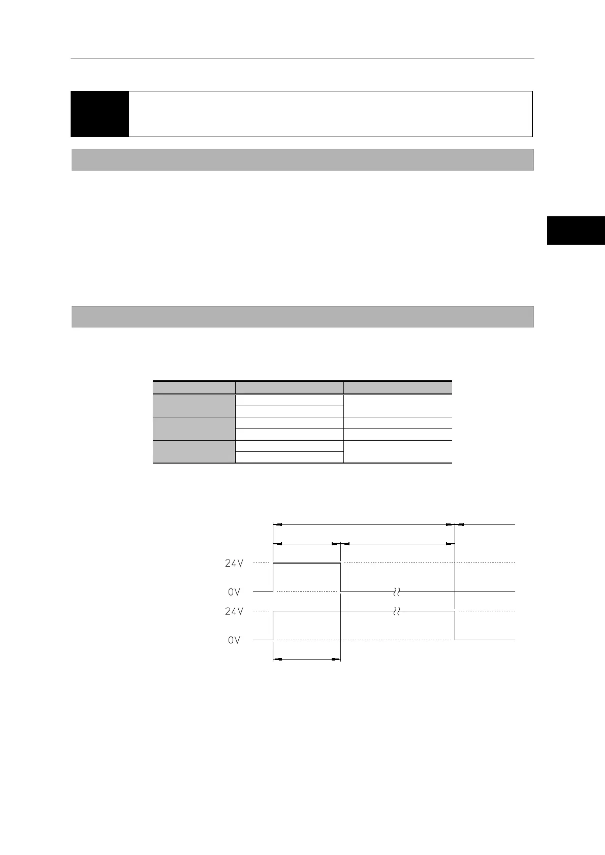
Supply the power upon brake release and during brake release retention, as shown below.
24VDC±10%
±
0VDC
Supply the power to the coils according to the following time chart.
Control the power supply so that the duration in which the power is supplied to the brake release coil
(gray/yellow) is 100ms or less. The brake will not be released only by the power supply to the brake
release retention coil. To release the brake, also supply the power to the brake release coil.
Wiring: Gray/Yellow (GND)
Brake release retention coil
Wiring: Blue/Yellow (GND)
 Loading...