11
PME-MP60/MP07
A0616-13.4 en HBM
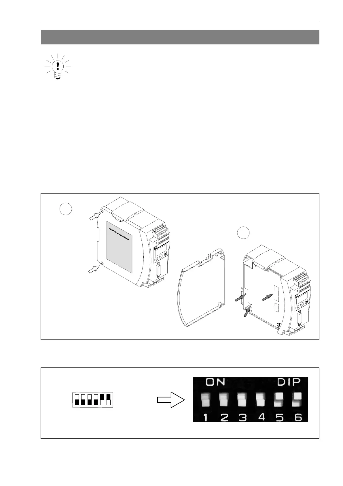
2 Selecting amplifier settings with DIP switches
NOTE
The adjustment/alteration of DIP switch settings must take place before
mounting the PME.
Various settings are defined with the aid of DIP switches. These are the
settings for
terminating resistance, frequency input signals, input connection
(asymmetric, symmetric), analogue output, synchronization, bus
terminating impedance, slope steepness
To set the DIP switches, you must proceed as shown in Fig. 2.1.
S5
S4
S10
S11
S12
Screw off
cover
1
2
S6
Fig. 2.1: Open housing, position of DIP switch
12
34
5
6
Example:
means
ON
Fig. 2.2: Switch convention