18
PME-MP60/MP07
A0616-13.4 enHBM
4 Connections
WARNING
Please take note of the safety instructions before putting the device into
operation.
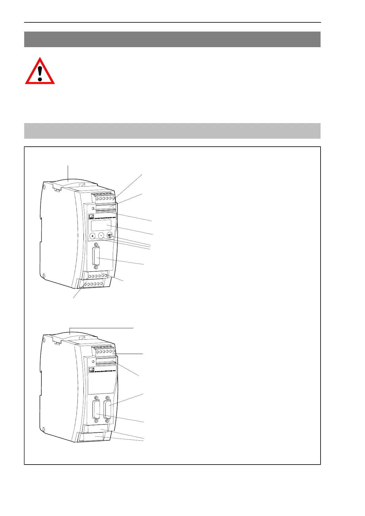
4.1 Functional overview of MP60/MP07
Terminal plug 1:
Voltage supply and CAN-bus, Synchronization
Transducer connection (15-pin D-Sub connector (male))
Terminal plug 3:
Potential-separated
1)
control inputs (24 V level), analogue output
Pressure-sensitive control keys
Two line LCD display
Terminal plug 2: (same pin assignment as terminal plug 1)
CAN adapter for PC/laptop connection, assigning
parameters via CAN-bus
Terminal plug 4:
Potential-separated control outputs (24V level), external power supply of control inputs
LED
Local linking of CAN-bus, supply voltage and synchronization between the modules
1)
Potential separation in relation to amplifier (measuring circuit) and supply voltage
Control inputs and outputs have the same reference potential
M
P
6
0
S
E
N
S
O
R
Terminal plug 1:
Voltage supply
Transducer connection (15-pin D-Sub connector
(male)) complete with transducer excitation for torque
transducers
Terminal plug 2: (same pin assignment as terminal plug 1)
MP60 module connection
MP60
MP07
Local linking of CAN-bus, supply voltage and
synchronization between the modules
Blank plates