Electrical connection
PAD4002A A4243-1.0 HBM: public 25
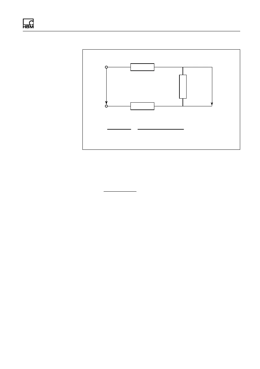
R
Cable
R
Cable
R
Sensor
U
Sensor
U
Amplifier
R
Sensor
R
Sensor
+ 2 @ R
Cable
U
Sensor
U
Amplifier
=
Fig. 6.3 Voltage ratios at the sensor based on cable
resistance
R
Cable
=
The resistance of a cable is calculated by
The variation of resistance with temperature is
with a
20
= 4.3 ∙ 10
−3
/ °C (temperature coefficient at 20°C)
The specific resistance ρ of copper at 20°C is
ρ ∙ length
cross-section
ρ
20
= 0.0169 Ω ∙ mm
2
/ m
R
Temp
= R
20
∙ (1 + a∙(t − 20))
When using HBM load cells (6‐wire configuration), in the
connection variant with inter-connected wires (pins 7 and
3 / pins 6 and 5), sensitivity is affected as shown in the
table below .