21©HBS Bolzenschweiss-Systeme GmbH & Co. KG
All rights reserved – Reprinting, in whole or in part, only with the approval of the manufacturer
9 Welding Process
9 Welding Process
Stud welding with tip ignition is divided into contact stud welding and gap stud wel-
ding. This stud welding unit may exclusively be used for contact stud welding and
gap stud welding.
9.1 Contact Stud Welding
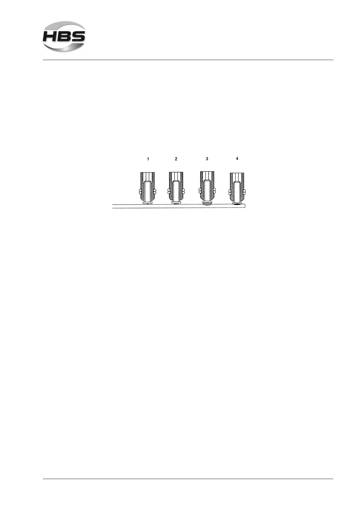
– The welding gun is placed onto the work piece (see gure, position 1). The wel-
ding element which projects above the welding gun support legs, is pushed back
tensioning a pressure spring.
– After positioning the welding gun against the workpiece, the operator presses
the welding gun trigger and starts the welding process; thus the current circuit is
closed.
– The capacitors of the stud welding unit are discharged. Because of the high
discharge current, the ignition tip evaporates explosion-like. The air gap between
welding element and workpiece is ionized (see gure, position 2), a light arc is
produced.
– The light arc melts the face of the welding element together with an area of the
workpiece of about the same dimension (see gure, position 3).
– Caused by the pressure spring, the welding element moves to the workpiece with
a speed of 0,5 to 1 m/s. The adjusted spring force controls the plunging speed of
the welding element.
– Higher plunging speed leads to shortened arc time and consequently to lower
welding energy with identical voltage setting.
– The light arc is cut as soon as the welding element touches the workpiece.
– Now the capacitors are short-circuited and the rest of the energy drains off (see
gure, position 4).
– The pressure spring continues to push the welding element into the weld pool.