The switching power supply can select the input voltage of 220 V or 110 V by the DIP switch, and
the default seng is 220V. Please adjust the DIP switch based on the actual AC voltage to avoid
damaging the equipment.
Note
●
The cable bare part should be no more than 8 mm. If possible, wear an insulaon cap at the end
of the bare cable. Make sure there's no bare copper or cable aer the wiring.
●
The Terminal L and the Terminal N cannot be wired reversely. Do not wire the input and output
terminal reversely.
●
To avoid people injury and device damage, when tesng, the ground resistance of the
equipotenal points should not be larger than 2 Ω。
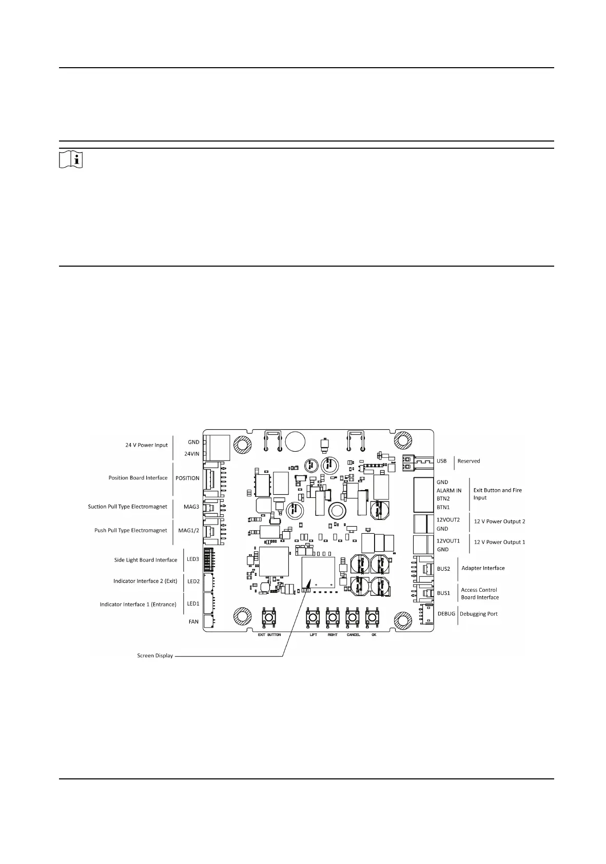
4.4 Terminal Descripon
4.4.1 Lane Control Board Terminal Descripon
The lane control board contains power input interface, exit buon and re input interface, access
control board interface, debugging port, indicator interface, etc.
The picture displayed below is the lane control board diagram.
DS-K3G501X Series Tripod Turnsle
11
 Loading...