Introduction
Chapter 3: Theory of Operation
Page 3 - 2 Hill-Rom® Basic Care™ Bed, Hill-Rom® 305 Manual Bed,
Hill-Rom® 405 Electric Bed Service Manual (MAN336 REV 2)
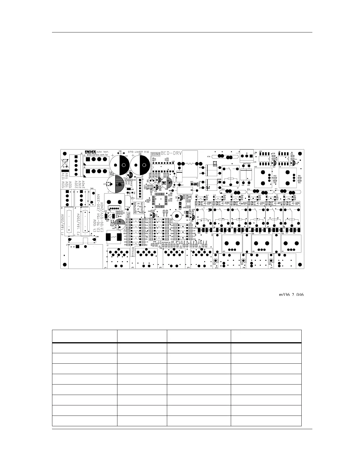
Transformer Configurations
The electric Basic Care™ Bed permits eight different input source voltages
with two transformers and various connector positions on the control board
(see figure 3-1 on page 3-2).
The control board is configured for either E1, E2, or E3 transformers.
Figure 3-1. Transformer Configurations
For the correct transformer configuration, refer to table 3-1 on page 3-2.
Table 3-1. Transformer Configurations
Input Source Voltage Transformer Primary Connection Secondary Connection
100 V E1 J9 J8
110 V E2 J9 J8
115 V E2 J9 J8
127 V E3 J9 J8
200 V E3 J6 J8
220 V E2 J6 J8
230 V E2 J6 J8
240 V E3 J6 J8