3 Product Description System Manual Modular Systems
Page 18 of 114 HI 800 191 E Rev. 2.02
3 Product Description
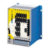
The modular HIMatrix F60 system is composed of a subrack and various modules inserted in
the subrack slots.
Slots 1 and 2 are reserved, all remaining slots can be freely occupied:
The wide slot 1 is always occupied with the power supply module (PS 01).
Slot 2 is always occupied with the CPU module (CPU 01).
The remaining slots can be freely occupied with all remaining module types.
The modular system F60 can also be connected to HIMatrix compact systems via safeethernet.
3.1 Modules
All modules of the HIMatrix F60 system are 6 rack units (RU) high, which correspond to
262 mm.
Specific slots are only reserved for the power supply module and the CPU module, see above.
Controller damage!
Inserting and removing the modules during operation is not permitted.
Prior to modifying the assembly, ensure that the controller is shut down!
After modifying a controller assembly, the corresponding user program must be adapted to the
change and reloaded.
Pluggable clamps located on the module's front plate are used to connect sensors and
actuators. The modules indicate the status of digital signals via LEDs located next to the
clamps.
3.1.1 Inputs
The module's input channels are used to transmit and adjust the signals between the sensors
and the microprocessor systems on the CPU module.
The controller continuously tests the safety-related modules. Depending on the fault, it switches
either only the affected channel off or the entire module, in which case the module is indicated
as faulty. The controller's operating system then sets the system user program's input value to
the safe value 0 (or the initial value).
Signal sources with their own voltage may also be connected instead of contacts. To this end,
the signal source ground must be connected to the input ground.
Surges on Digital Inputs
Due to the short cycle time of the HIMatrix systems, a surge pulse as described in EN 61000-4-
5 can be read in to the digital inputs as a short-term high level.
To prevent malfunctions, take one of the following measures for the application:
Install shielded input wires to prevent surges within the system.
Activate noise blanking: a signal must be present for at least two cycles before it is
evaluated.
Caution: This action increases the system's response time!

 Loading...