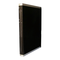
3 Product Description X-AI 32 01
Page 10 of 58 HI 801 021 E Rev. 4.00
3 Product Description
The X-AI 32 01 analog input module is intended for use in the programmable electronic
system (PES) HIMax.
The module can be inserted in any of the base plate slots with the exception of the slots
reserved for system bus modules. For more information, refer to the System Manual
(HI 801 001 E).
The module is used to evaluate up to 32 analog input signals.
The module has been certified by the TÜV for safety-related applications up to SIL 3
(IEC 61508, IEC 61511 and IEC 62061), Cat. 4 (EN 954-1) and PL e (EN ISO 13849-1).
Refer to the HIMax Safety Manual (HI 801 003 E) for more information on the standards
used to test and certify the modules and the HIMax system.
3.1 Safety Function
The module measures the current of the connected devices with safety-related accuracy,
providing the transmitter supply with a guaranteed minimum voltage.
The safety function is performed in accordance with SIL 3.
3.1.1 Reaction in the Event of a Fault
If a fault occurs, the module adopts the safe state and the assigned input variables transmit
the initial value (default value = 0) to the user program.
The initial values must be set to 0 to ensure that the input variables transmit the value 0 to
the user program if a fault occurs. If the raw value is evaluated instead of the process
value, the user must program the monitoring function and the value in the event of faults
from within the user program.
The module activates the Error LED on the front plate.
3.2 Scope of Delivery
The module must be installed on a suitable connector board to be able to operate. If a FTA
is used, a system cable is required to connect the connector board to the FTA. Connector
boards, system cables and FTAs are not included within the scope of delivery.
The connector boards are described in Chapter
3.6, the system cables are described in
Chapter
3.7. The FTAs are described in own manuals.

 Loading...