3 Product Description X-AI 32 01
Page 22 of 58 HI 801 021 E Rev. 4.00
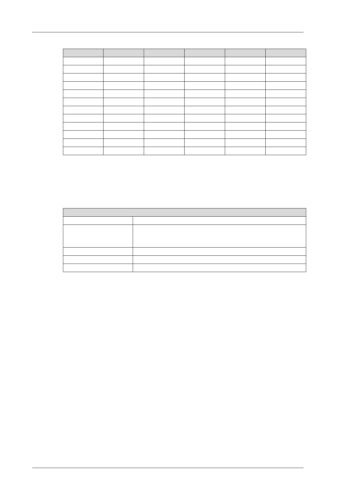
Pin no. Designation Signal Pin no. Designation Signal
1 25a S25+ 1 26a S26+
2 25b AI25+ 2 26b AI26+
3 25c AI25- 3 26c AI26-
4 27a S27+ 4 28a S28+
5 27b AI27+ 5 28b AI28+
6 27c AI27- 6 28c AI28-
7 29a S29+ 7 30a S30+
8 29b AI29+ 8 30b AI30+
9 29c AI29- 9 30c AI30-
10 31a S31+ 10 32a S32+
11 31b AI31+ 11 32b AI32+
12 31c AI31- 12 32c AI32-
Table 13: Terminal Assignment for Connector Boards with Screw Terminals
Cable plugs attached to the connector board pin headers are used to connect to the field
zone.
The cable plugs feature the following properties:
Connection to the field zone
Cable plugs 8 pieces, with 12 poles
Wire cross-section 0.2…1.5 mm
2
(single-wire)
0.2…1.5 mm
2
(finely stranded)
0.2…1.5 mm
2
(with wire end ferrule)
Stripping length 6 mm
Screwdriver Slotted 0.4 x 2.5 mm
Tightening torque 0.2…0.25 Nm
Table 14: Cable Plug Properties
 Loading...