4 Start-up X-AI 32 01
Page 30 of 58 HI 801 021 E Rev. 4.00
4.2 Mounting and Removing the Module
When replacing an existing module or mounting a new one, follow the instructions given in
this chapter.
When removing the module, the connector board remains in the HIMax base plate. This
saves additional wiring effort since all field terminals are connected via the connector board
of the module.
4.2.1 Mounting a Connector Board
Tools and utilities
Screwdriver, slotted 0.8 x 4.0 mm
Matching connector board
To install the connector board
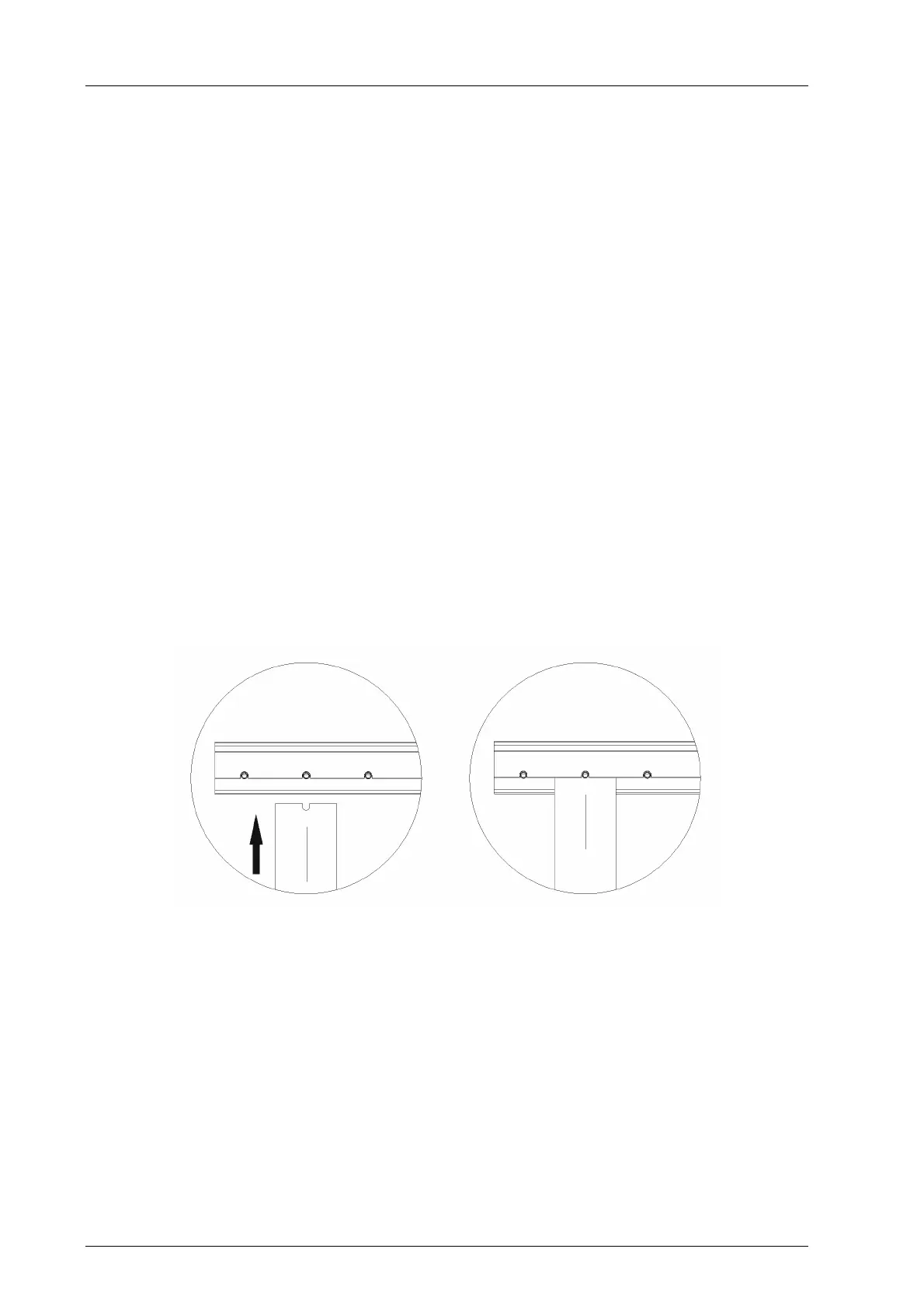
1. Insert the connector board into the guiding rail with the groove facing upwards (see
following figure). Fit the groove into the guiding rail pin.
2. Place the connector board on the cable shield rail.
3. Secure the two captive screws to the base plate. First screw in the lower than the upper
screw.
To remove the connector board
1. Release the captive screws from the base plate.
2. Lift the lower section of the connector board from the cable shield rail.
3. Remove the connector board from the guiding rail.
Figure 10: Inserting the Connector Board
 Loading...