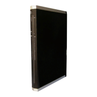
X-AI 32 01 Table of Contents
HI 801 021 E Rev. 4.00 Page 3 of 58
Table of Contents
1 Introduction ............................................................ 5
1.1 Structure and Use of this Manual......................................................................... 5
1.2 Target Audience..................................................................................................... 5
1.3 Formatting Conventions ....................................................................................... 6
1.3.1 Safety Notes ............................................................................................................ 6
1.3.2 Operating Tips ......................................................................................................... 7
2 Safety...................................................................... 8
2.1 Intended Use .......................................................................................................... 8
2.1.1 Environmental Requirements................................................................................... 8
2.1.2 ESD Protective Measures........................................................................................ 8
2.2 Residual Risk ......................................................................................................... 9
2.3 Safety Precautions................................................................................................. 9
2.4 Emergency Information......................................................................................... 9
3 Product Description .............................................. 10
3.1 Safety Function.................................................................................................... 10
3.1.1 Reaction in the Event of a Fault............................................................................. 10
3.2 Scope of Delivery................................................................................................. 10
3.3 Type Label ............................................................................................................ 11
3.4 Structure............................................................................................................... 11
3.4.1 Block Diagram........................................................................................................ 12
3.4.2 Indicators ............................................................................................................... 13
3.4.3 Module Status Indicators ....................................................................................... 14
3.4.4 System Bus Indicators ........................................................................................... 15
3.4.5 I/O Indicators.......................................................................................................... 15
3.5 Product Data......................................................................................................... 16
3.6 Connector Boards................................................................................................ 18
3.6.1 Mechanical Coding of Connector Boards .............................................................. 18
3.6.2 Coding of X-CB 008 Connector Boards ................................................................. 19
3.6.3 Pin Assignment for Connector Boards with Screw Terminals................................ 20
3.6.4 Terminal Assignment for Connector Boards with Screw Terminals....................... 21
3.6.5 Pin Assignment for Connector Boards with Cable Plug......................................... 23
3.6.6 Pin Assignment for Connector Boards with Cable Plug......................................... 24
3.6.7 Connector Board Redundancy using Two System Base Plates ............................ 25
3.6.8 Pin Assignment for X-CB 008 05 ........................................................................... 26
3.7 System Cable ....................................................................................................... 27
3.7.1 System Cable X-CA 005 ........................................................................................ 27
3.7.2 System Cable X-CA 009 ........................................................................................ 28
3.7.3 Cable Plug Coding................................................................................................. 28

 Loading...