153
Controlling Integration with External Signals
8.2 Controlling Integration with External Signals
Integration can be started and stopped, and integration data can be reset with 2-level (0 to 5 V)
logic signals or by shorting/opening contact signals of the instrument’s external control interface.
DANGER
Do not input a voltage in excess of the maximum input voltage to the
external input terminal.
Doing so may damage the instrument, resulting in serious bodily injury.
Cable connections
Required equipment: External device to control this instrument, and the 9444 Connection Cable
1
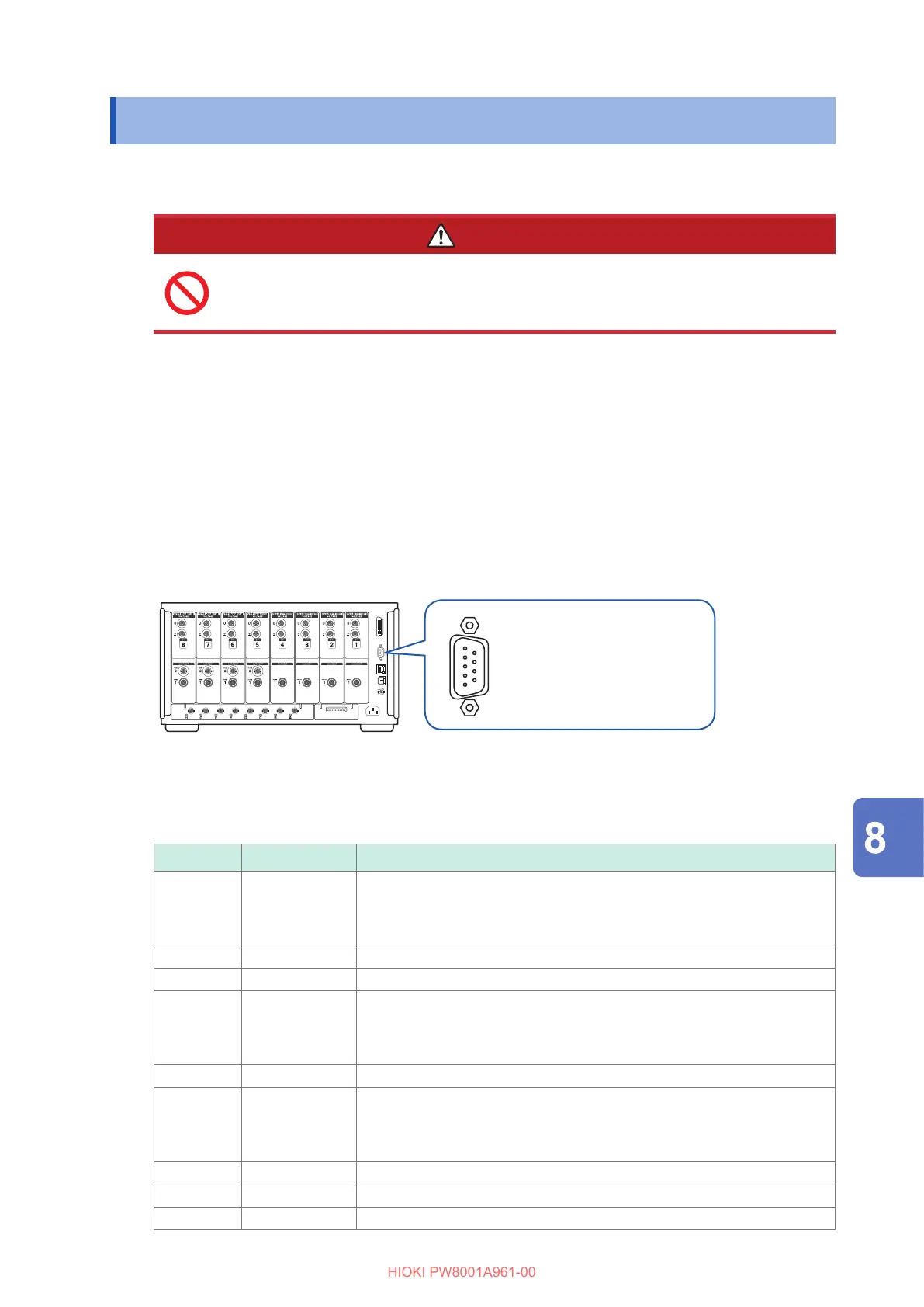
Connect one end of the 9444 Connection Cable to the instrument’s 9-pin D-sub connector,
and tighten the screws to secure the connector in place.
2
Connect the other end of the 9444 Connection Cable to the external device being connected
to this instrument.
Either use the 9-pin D-sub female connector on the cable or cut o the male connector on the 9444
Connection Cable and hard-wire it to the device, using the internal cable colors for reference.
9-pin D-sub plug (male)
Locking screws: #4-40
Device for controlling this instrument
Prepare a device and the cable so that the functions are assigned to the pins listed below. Leave
unused pins open.
Pin no. Cable color Functions
1 Brown Start/stop integration
When this pin’s level changes from high (5 V or open) to low (0 V or
shorted), integration will start. When it changes from low to high, integration
will stop.
2 Red Unused
3 Orange Unused
4 Yellow Hold
When this pin’s level changes from high (5 V or open) to low (0 V or
shorted), the display will be held. When it changes from low to high, the
hold will be canceled.
5 Green GND
6 Blue Resetting integrated values
When this pin’s level has been low for at least 200 ms, integrated values
will be reset.
This function is valid only while integration is stopped.
7 Purple Unused
8 Gray Unused
9 White Unused
Connecting External Devices
 Loading...


