41
Setting Wiring Mode and Conguring Current Sensor Settings
2.5 Setting Wiring Mode and Conguring Current
Sensor Settings
This section describes how to set wiring modes based on the number of channels with which the
instrument is equipped and the lines to be measured.
To combine dierent input modules for multiple channels (for measurement on multi-phase
systems), connect the same current sensors to all the channels to be combined.
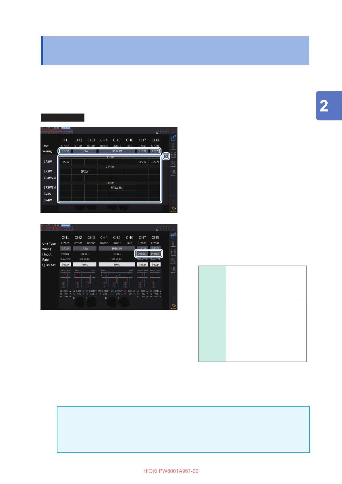
Display screen [INPUT] > [WIRING]
11
33
22
1
Tap the button to select a wiring mode
for each channel.
The Settings window will open.
2
Select a wiring mode from among 1
module, 2 modules, and 3 modules.
See “Wiring mode” (p. 42).
When dierent types of input modules are
connected to a single wiring conguration, the
circumference of the wiring button is displayed
in yellow.
3
Tap [
×
] to close the setting window.
4
Only for U7001, select the current
sensor to be used for each channel.
Always connect the same type of current
sensors within the same wiring conguration.
Probe1
Select this option when the
current sensor is connected to
the Probe 1 terminal (for high-
performance current sensors).
The rate is automatically set.
Probe2
Select this option when the
current sensor is connected to
the Probe 2 terminal (for current
sensors).
Set the rate individually. Tap the
rate-selection button, and then
select the rate or the product
model name of the connected
current sensor.
44
When using a current sensor whose rating can be switched, match the rating of current sensors in
the same line.
If a wiring pattern using multiple channels is selected, the parameters that can be set for each
channel (such as the voltage range) are unied to those of the rst channel.
IMPORTANT
If dierent types of input modules are used in the same wiring conguration, the measurement
accuracy of the U7001 applies to the measurement accuracy of all measured values within the
wiring system. The accuracy of values measured with the U7005 is also the same as that of the
U7001.
Preparing for Measurement
 Loading...


