13
4. FAMILIARIZATION WITH CONTROLS AND PARTS
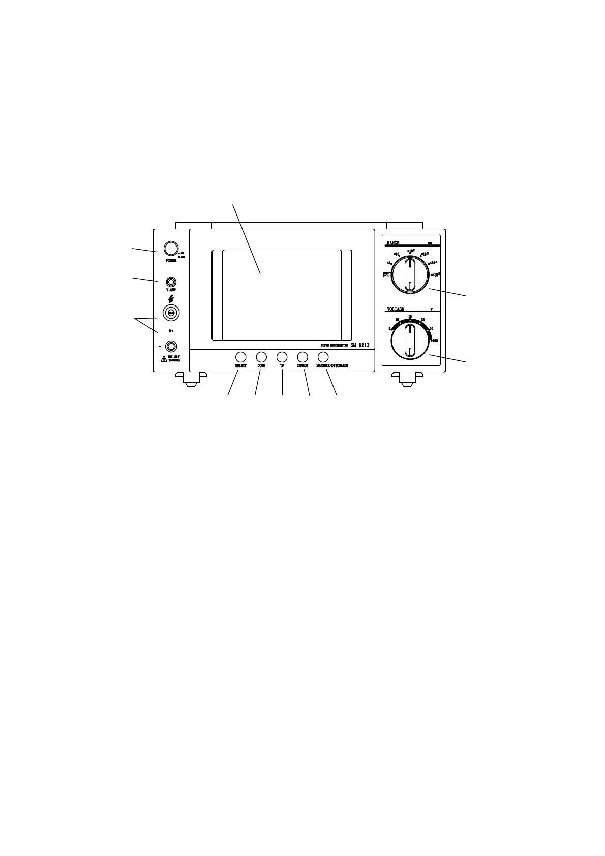
4.1 Front Panel
The figure below shows the front panel of the SM-8200 Series. However, note that the values for
the two knobs on the right are represented by those of the SM-8213.
Fig. 4.1 Front Panel
① LCD Display: This is a 320×240 dot liquid crystal display module.
This shows measured results, measuring conditions and a variety of
data settings.
② POWER Switch: This is a power switch to turn on or off the instruments.
A press of this switch in the released position turns ON the unit.
A press of this switch in the pushed position turns OFF the unit.
③ V. OUT Indicator: This indicator lights when the Rx /+ measuring
terminals carry a measuring voltage across them.
④
Rx /+ Measuring Terminals: These terminals carry a selected measuring
voltage across them to measure the insulation resistance of a sample
via a pair of measuring rods or electrodes.
Note: Each of the terminals is incorporated with a plug insertion
detector switch. Unless otherwise this switch is turned on by a
full insertion of the plug of the measuring rod or electrode, the
output voltage circuit cannot be completed – no output.
Pease be careful when inserting or removing the plug so as not
to cause any impact on the detection switch inside the terminal.
①
⑪
⑩
⑨⑧⑦
⑥⑤
④
③
②