15
⑱⑰ ⑯ ⑮
⑭⑬⑫
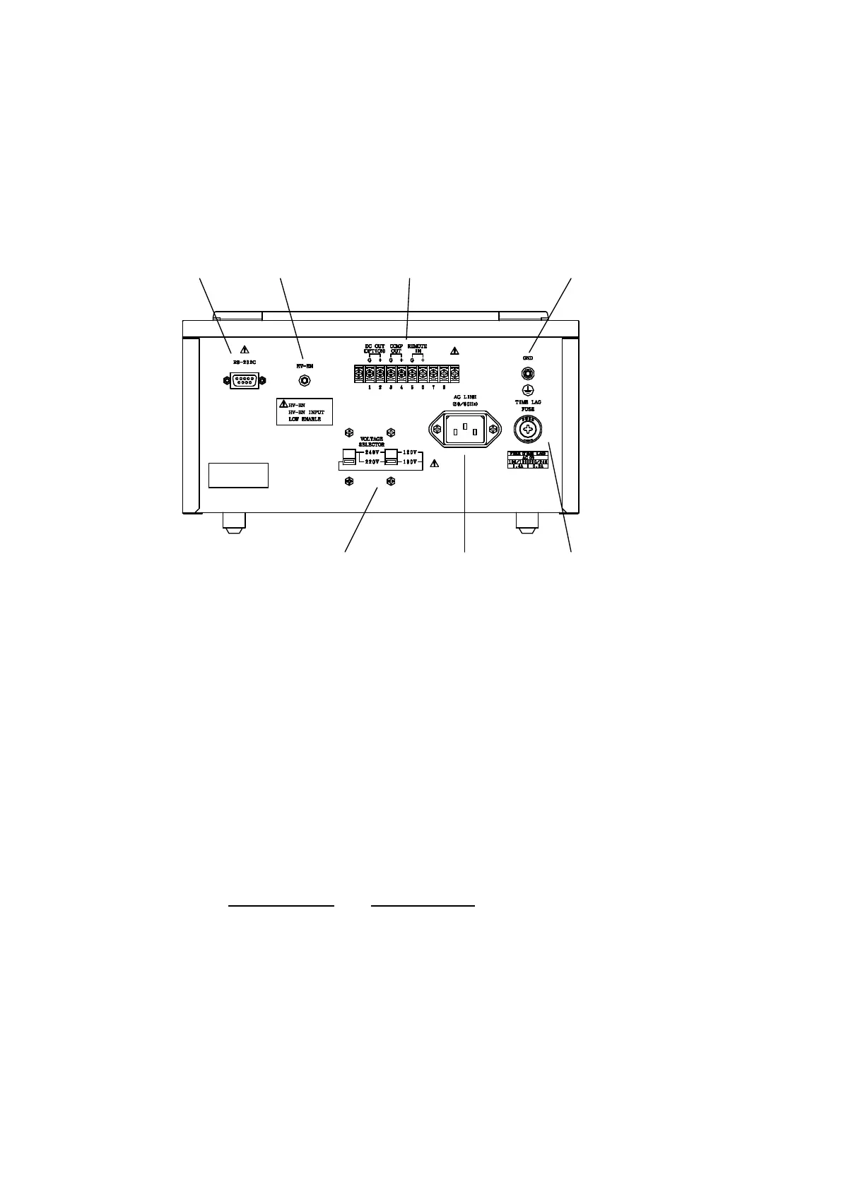
4.2 Rear Panel
The figure below shows the rear panel of the SM-8200 Series. However, note
that the VOLTAGE SELECTOR switches are set for the operation from 100 V
AC line.
Fig. 4.2 Rear Panel
⑫
VOLTAGE SELECTOR Switches: These two switches are to be set in
accordance with the local AC line voltage (50 or 60 Hz) for the
instrument.
For a proper setting, see 1.3 Setting VOLTAGE SELECTOR Switches.
For line voltage change between 100 V/120 V and 220 V/240 V, the
power fuse amperage must be also changed accordingly.
⑬
AC LINE Receptacle: This connects the accessory power cord.
⑭
TIME LAG FUSE Holder: This holder contains a time lag fuse in a glass
tube. The amperage of the fuse must agree with the local AC line
voltage from which the unit is powered.
AC Line Voltage
Fuse Amperage
100 V/120 V (50/60 Hz) 0.4 A
220 V/240 V (50/60 Hz) 0.2 A
Note: When the AC line voltage for the unit is changed after receipt of
your super megohmmeter, check the fuse amperage.
⑮ GND Terminal: This is a ground terminal connected to the chassis of the
unit.