17
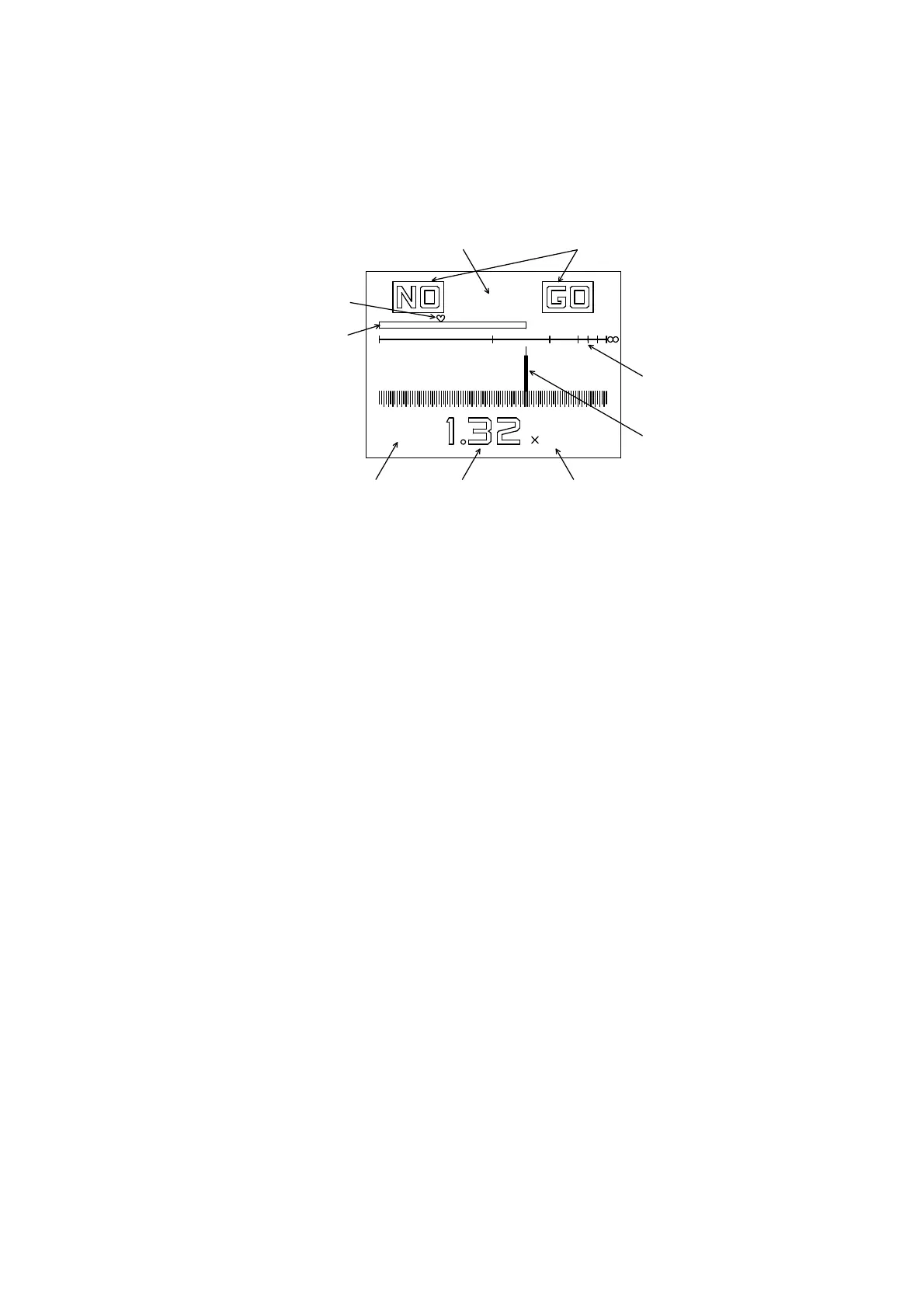
4.3 Measuring Display
In the measuring mode, the LCD display shows the resultant measured
resistance value and its NO/GO judgment, as well as the measuring voltage
and time.
Fig. 4.3
① Test Voltage Indication: This shows the test voltage set with the VOLTAGE
selector switch.
②
Measured Resistance Indication: This shows the measured resistance in
real time. When the measuring time is up, the final value is held
until the next measurement will start.
③
Measuring Range Indication: This shows the measuring range set with the
RANGE selector switch.
④
Analog Indicator: This shows the measured resistance value in analog
referred to the analog resistance scale.
⑤
Analog Resistance Scale: This shows the scale for the analog indicator
reading. When the measuring voltage is changed, the scale and
values are changed, accordingly.
⑥ NO/GO Comparison Judgment Indication: When the NO/GO comparison
judgment function is set on, a judgment of resultant resistance can
be done referred to preset high/low limits. When the comparison
judgment value is set to 000, the function becomes off.
⑦ Timer Count Indication: This is a count-down timer shown in seconds.
When the timer is set to 000 sec., the function becomes invalid.
⑧
Comparison Judgment Value Mark: When the comparison judgment
function is set on, a heart mark appears at a position showing the
set value on the measured resistance bar graph.
⑨
Measured Resistance Bar Graph: This shows the measured resistance as
a length of the bar.
100V
⑦⑥
⑨
⑧
⑤
④
③②①
3
s
MΩ
10
2010521.5
000