20
Installation BAT
Release
05
03/2013
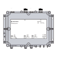
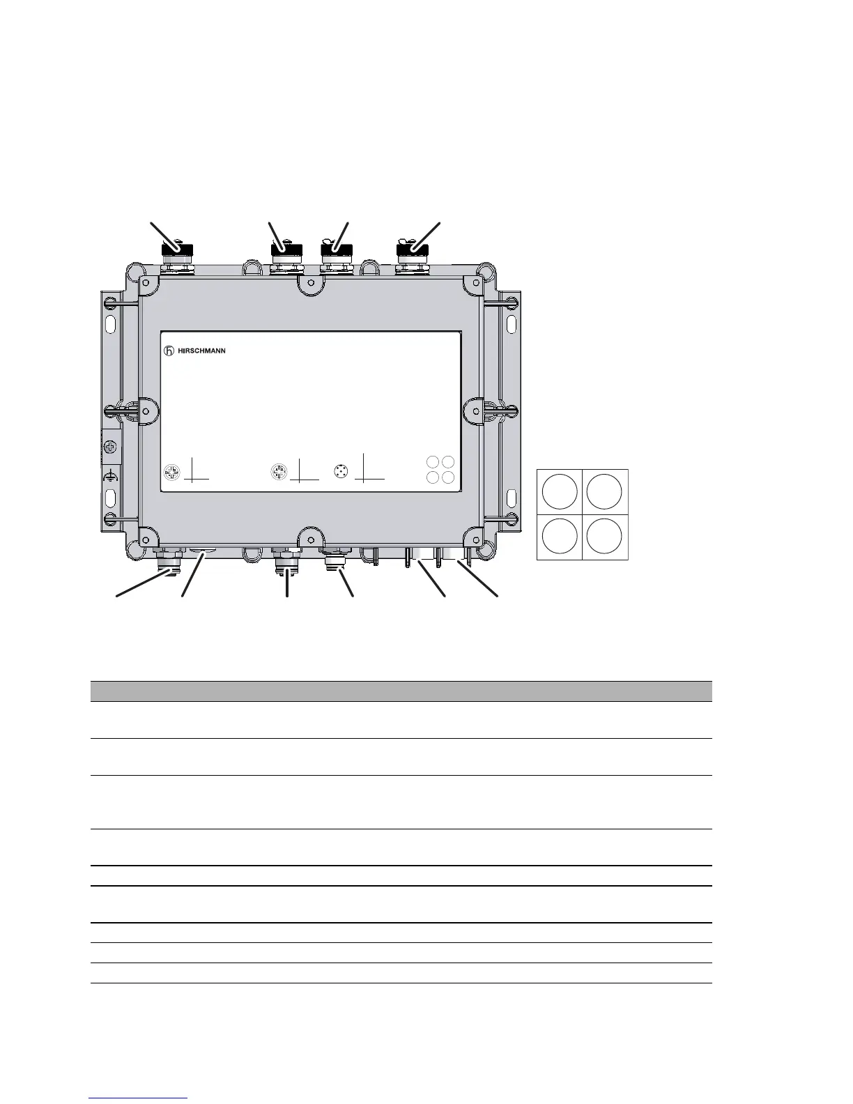
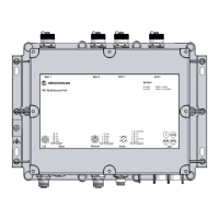
1.2 Interfaces and control elements
1.2.1 BAT54-F
The device is equipped with the following connectors and operation
elements:
Interfaces and display and control elements
1 V.24 Serial interface, 4-pin M12 socket with A coding, data rate min. 19.2 kbit/s, max.
115 kbit/s, connector for serial configuration cable
2 Reset Reset button behind a removable IP67 cap
restarts the device or resets the configuration
3 Ethernet Ethernet port:
4-pin M12 socket with D coding, 10/100BASE-TX, Autosensing, Power over
Ethernet (PoE), automatic MDI/MDIX recognition (no crossover cable required)
4 Power Power supply connector for safety extra-low voltage (SELV/PELV), 5-pin M12
plug
5 LED 4 display elements (power, LS/DA, WLAN1, WLAN2)
6 AUX 2 Auxiliary connector for the second WLAN module for connecting external
antennas
7 AUX 1 Auxiliary connector for the first WLAN module for connecting external antennas
8 Main 2 Main connector for the second WLAN module for connecting external antennas
9 Main 1 Main connector for the first WLAN module for connecting external antennas