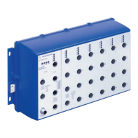
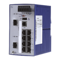
PowerMICE
Release
01
04/2014
27
2.2.5 Adjusting DIP switch settings on basic module
The 6-pin DIP switch on the bottom panel of the basic module provides you
with the following options:
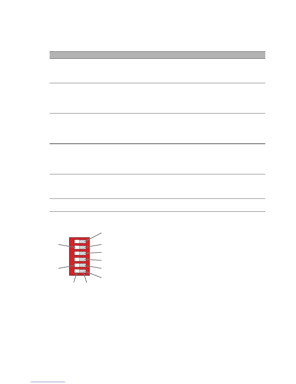
Figure 12: 6-pin DIP switch on basic module
1 – Switch 1, position ON, function: Redundancy Manager (RM)
2 – Switch 2, position ON, function: module 2, port 1 and port 2
3 – Switch 3, position ON, function: stand-by
4 – Switch 4, position ON, function: HIPER-Ring
5 – Switch 5, position ON, function: DIP configuration
DIP switch Function Default setting
RM (Redundancy
Manager)
Switch the RM (Redundancy Manager)
function on and off when the HIPER-Ring
function is activated (see “User Manual -
Redundancy Configuration”).
OFF position (RM function
deactivated)
Ring port Select the port for the HIPER-Ring. The
changes to the switch setting are taken
over after the restart.
In the ON position, ports 1 and 2 in module
2 form the connection for the HIPER-Ring.
OFF position (ports 1 and 2 in
module 1 form the connection
for the HIPER-Ring).
Stand-by With the redundant coupling of rings, you
assign the redundancy function to the
PowerMICE in the redundant line (see
“User Manual - Redundancy
Configuration”).
OFF position (normal
operation)
HIPER-Ring
a
a. Control port: module 1, port 3; coupling port: module 1, port 4
Switch the HIPER-Ring functions on and
off. When the function is switched off, you
can use the Ring ports as normal ports.
In the ON position, RSTP (Rapid
Spanning Tree) is globally deactivated.
OFF position
Software
configuration / DIP
configuration
Give the software configuration
precedence over the DIP switch position.
In this case, the other switch positions are
meaningless.
OFF position (software
configuration has precedence)
Service Switch the device to the service mode. OFF position (normal
operation)
OFF ON
8 7
10
9
1
2
3
4
5
6
 Loading...