PowerMICE
Release
01
04/2014
31
Failure of the redundancy.
The removal of the AutoConfiguration Adapter.
The following condition is also reported in RM mode:
Ring redundancy guaranteed. By default, there is no ring redundancy
monitoring
Pull the terminal block off the device and connect the voltage supply
lines and the signal lines.
2.2.9 Installing the terminal blocks; start-up procedure
Mount the terminal blocks for the voltage supply and the signal contact on
the bottom of the device using the snap locks.
Make sure the snap lock latches securely in place.
By connecting the voltage supply via the terminal blocks, you start the
operation of the device.
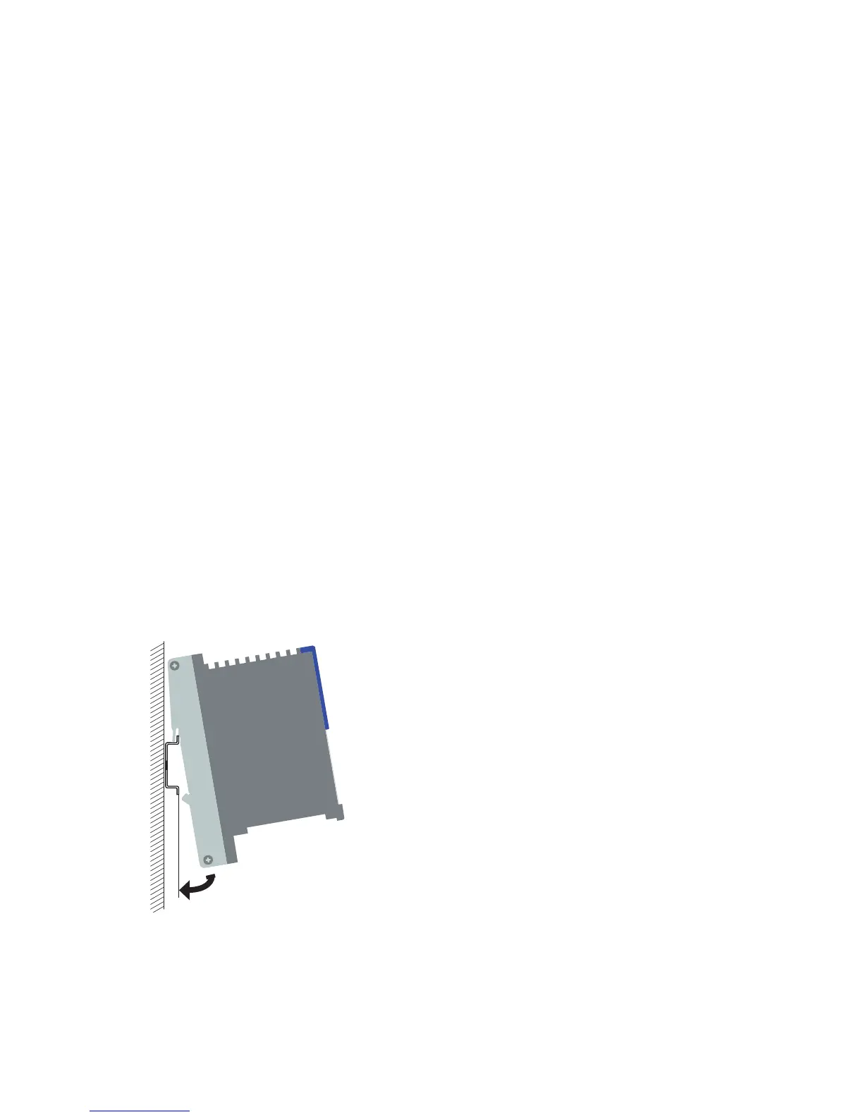
2.2.10 Installing the device on the DIN rail, grounding
Mount the device on a 35 mm DIN rail in accordance with DIN EN 60175.
Attach the upper snap-in guide of the device into the DIN rail and press
the device down against the DIN rail until it snaps into place.
Note: The shielding ground of the industrial connectable twisted pair lines is
connected to the lower panel as a conductor.
Figure 13: Assembly
Grounding
The lower panel of the device housing is grounded by means of the DIN
rail and optionally by means of the separate ground screw (see fig. 2).
 Loading...