21
// 3
……
EE EEE
……
……
ġ
Ģ
Step 3
Continuously press the temperature regulation key③
“ġ”, “Ģ
items are shown the right. The set temperature display
[Temperature Control] Key.
No. Items for Code Unit Example Notes to Parameters
1 target water temperature °C 45 set temperature for wire controller
2
water module water inlet temperature
°C 30 actually measured temperature
3 water module water outlet temperature °C 35 actually measured temperature
4
water module liquid pipe
°C 34 actually measured temperature
5
heat exchanger water outlet temperature
°C 40 actually measured temperature
6 environmental temperature °C 25 actually measured temperature
7
water module gas pipe temperature
°C 60 actually measured temperature
8 domestic water tank water temperature °C 53 water tank test temperature
9 outdoor unit evaporation temperature °C 6 actually measured temperature
10 top vent temperature of compressor °C 70
actually measured temperature
11
thermally sensitive resistance temperature of
wire controller
°C 30
standby (actually measured room temperature)
12 set water temperature of domestic water tank °C 55 -
13 standby °C 30 -
14 standby °C 30 -
15 environmental temperature (average) °C 25
Average calculated value of environmental
temperature
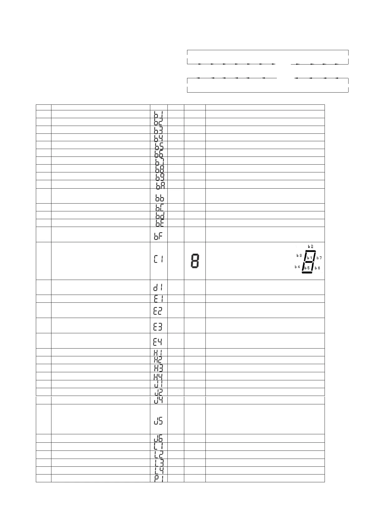
16 water module input/output state
b1: temperature control input state
b2:forced temperature control stop input
b3 water module water pump run state
b4 water module electric heating state
b5 electric heating state of domestic water tank
17 reason for stopping 10
display the reason for previous stop, see details
in technical information II
18 occurrences of abnormalities times 5 -
19
occurrences of instantaneous power failure of
indoor unit
times 6
-
20
occurrences of errors of communication
between wire controller and water module
times 7
-
21
occurrences of abnormalities of frequency
inverter
times 8
-
22 air vent pressure MPa 29 outdoor unit pressure 10 times value
23 air suction pressure MPa 6 outdoor unit pressure 10 times value
24 target vent pressure MPa 23
outdoor unit pressure 10 times value
25 running frequency of compressor Hz 80
-
26 water module capacity 140 automatically identified by machine type
27 outdoor unit number WP01 -
28
refrigerant system number 0 -
29
running state 0
shut down 0
floor heating temperature control ON 1 OFF 2
Fan coil temperature control ON 3 OFF 4
Water tank temperature control ON 5 OFF 6
30
wire controller number of water module V11
-
31
expansion valve opening of water module 30
according to maximum opening percentage
32
expansion valve opening of outdoor unit 20
according to maximum opening percentage
33
expansion valve opening of outdoor unit 20 according to maximum opening percentage
34
expansion valve opening of outdoor unit 20 according to maximum opening percentage
35
working current of compressor 12 -
[Temperature Control ] Key
[Temperature Control ] Key
area displays
item code.
See the table below for “ Mode 1” data.
Check
CHECK
”, and the circulating display of
CHECK
CHECK