S S
F
P
30
Water Inlet
Ball V alve
Isolate water circulation after ball valve in
water inlet and outlet are closed. Water
make-up inlet in ball valve supplements
water to water circulating system.
Water O utlet
Lliquid pipe
Gas pipe
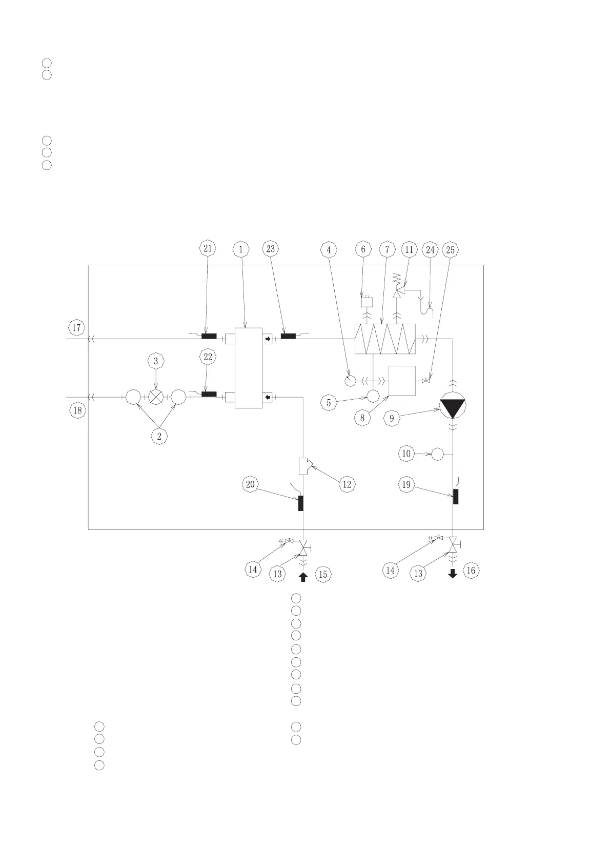
6.3 System Cycle Diagram
① Plate H eat Exchanger
② Filter
③ Electrical Expansion V alve
④ Pressure G age
⑤ Water Pressure Switch
⑥ Automatic V ent V alve
⑦ Electrical H eater
⑧ ExpansionT ank
⑨ Water Pump
⑩ Water flow switch
Safety V alve
Water Filter
Ball V alve
Water M ake-up Inlet
Water Inlet
Water Outlet
Refrigerant Gas Pipe
Refrigerant Liquid Pipe
Water O utlet T emperature
Water Inlet T emperature
Gas Pipe T emperature
Liquid Pipe T emperature
Water O utlet T emperature of
Plate H eat Exchanger
Drain Pipe
Charging Port of Expansion
T ank
16
17
18
19
20
11
12
13
14
15
16
17
18
19
20
21
22
23
24
25