φ 9.53 40
φ 12.7 60
34
Right
Wrong
Seal with Adhesive Tape or Sealing Cap
Do not put pipe down on the ground
8. Refrigerant and Water Pipe
R410A refrigerant is adopted. When leakage and air
tight test are made, do not mix with oxygen,
acetylene, inflammable gas and poisonous gas. They
are very dangerous and may cause explosion.
Recommend using compressed air, nitrogen or
refrigerant.
8.1 Refrigerant Pipeline and Piping
(1) Copper pipe are prepared on site.
(2) Pipe dimension are selected as follows.
Unit (mm)
(3) Select copper pipe without dust and moisture.
Blow dust and impurity in pipeline with nitrogen or
dry air before pipeline is mounted.
8.2 Connect Refrigerant Pipeline
(1) Confirm stop valve is closed. Gas and liquid pipe
are located as shown in Fig.8.1:
(2) As shown in Fig.8.2, screw up nut cap. Refer to
the torque required below:
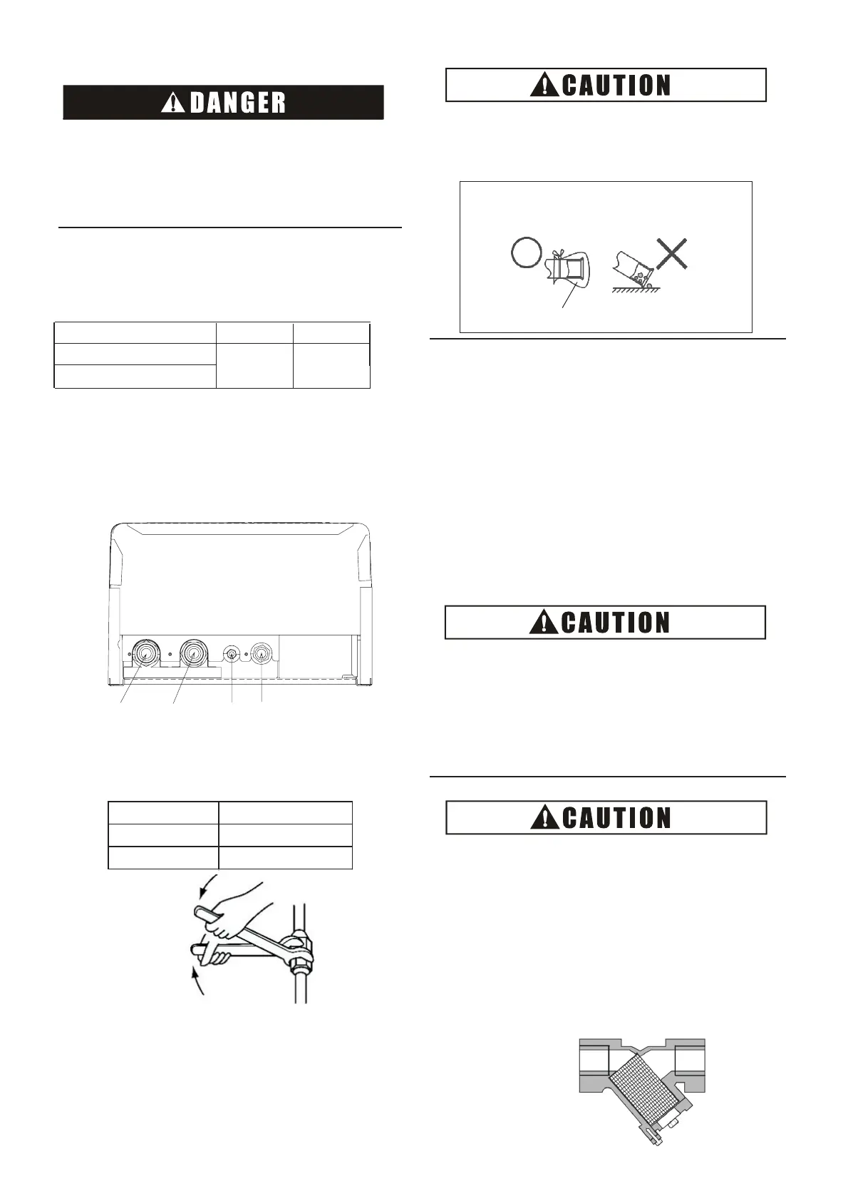
Water
Inlet
Water
Outlet
Gas
Pipe
Liquid
Pipe
Fig.8.2 Screw up Nut Cap
Pipe Diameter
Torque(N•m)
(3) Heat preservation of refrigerant pipe
After pipe is connected, heat preservation
material on site should be used to keep gas pipe,
liquid pipe and connecting nut warm, and wrap
the pipe with adhesive tape, avoiding heat
dissipation condensation on surface of pipeline.
●
When the pipe passes through holes, pipe head
should be sealed by sealing cap.
●
Seal the pipe end with sealing cap or adhesive
tape. Do not directly put pipe down on the ground.
(4) Charging and discharging of refrigerant
Operate according to installation and maintenance
manual of outdoor unit.
8.3 Connect Water Pipeline
(1) The connecting location of water pipeline is seen
in Fig.8.1.
(2) Install ball valve
There are two ball valves provided with the unit.
For convenience of repair and maintenance, install
the ball valves on water inlet and outlet pipes
of water module. Installation location refers to the
section 6.2 Main Parts.
● When ball valve is mounted, rubber gasket must
be mounted (accompanied with the unit),
otherwise water leakage may be caused.
●
Note the location of ball valve, and the direction of
ball valve and drain valve, which are essential to
maintenance.
● Screw up ball valve by using two wrenches.
R410A refrigerant is adopted. When leakage and air
tight test are made, do not mix with oxygen,
acetylene, inflammable gas and poisonous gas. They
are very dangerous and may cause explosion.
Recommend using compressed air, nitrogen or
refrigerant.
Type
Gas pipe Liquid pipe
Φ 15.88
Φ 9.53
AHM-080FJFAA
AHM-160FJFAA
Fig.8.1 Location of Refrigerant and Water Pipeline
(3) Additional water strainer
●
Provide a 50 mesh or more water strainer at the
water inlet side of water piping. Otherwise, damage
to the plate heat exchanger may occur. In the plate
heat exchanger, water flows through a narrow space
between the plates.Therefore, there is a possibility
that freezing or corrosion may occur if foreign
particles or dust clog the flow of water between the
plates.
Water Strainer
(50 mesh or more recommended)
This is not required when cooling function is not used.
Water Flow Direction →