Rear.
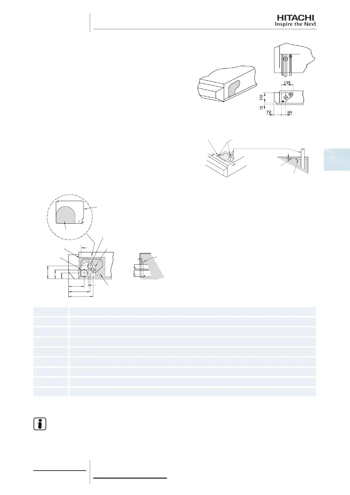
4 Install the pipes through it and seal them using the insulation supplied, as indicated below.
Top.
Rear.
P
1
2
3
4
5
6
7
8
9
P
1
2
3
4
5
6
9
125
*145
54
83
38
95
1
Sealing plate supplied (0.8x118x142 mm)
2 Gas refrigerant pipe
3 Liquid refrigerant pipe
4 Seal with insulation
5 Sec. P.P.
6 M4 screw
7 Sealing plate
8 M4 screw
9 Knockout hole
¿ Drain pipe installation
N O T E
The normal direction for connecting the drain hose is on the right side (when the unit is seen from the outlet grille
side). The connection can be made from the left side if there are construction elements of the building around it.
Sealing plate
Sealing plate
M4 screw
Refrigerant piping
Sealing with
insulation. Sec. A-B
Rear side connection
1. Knockout hole
M4 screws
Sealing plate
Sealing plate
Seal with insulation Section A - B
Refrigerant pipe
3 Piping work and
refrigerant charge
95
SMGB0063 rev. 1 - 10/2010
3
 Loading...


