Chapter 4 Explanation of Functions
4-37
4.2.29 Electronic thermal protection
The electronic thermal protection function allows you to protect the
motor against overheating. Make settings of this function based on
the rated current of the motor. The inverter will trip for overheat
protection according to the settings.
This function provides optimum overheat protection that is also
designed with the lowering of the motor's cooling performance at
low speeds in mind.
You can configure this function so that the inverter outputs a
warning signal before it trips for electronic thermal protection.
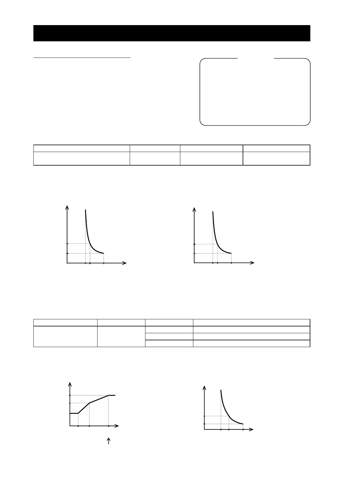
(1) Electronic thermal level
Electronic thermal setting (calculated
within the inverter from current output)
0.2 to 1.0 x rated current
(Example) Setting on the SJ700-150LFF(0.4-55kW)
CT mode rated current: 64 A
Range of setting: 12.8 A (20%) to 64.0 A (100%)
When 64 A is set as the electronic thermal setting (b012),
the time-limit characteristic is as shown on the right.
(2) Electronic thermal characteristic
The frequency characteristic set as the electronic thermal characteristic is integrated with the value of "b012", "b212",
or "b312".
The cooling-fan performance of a general-purpose motor lowers when the motor speed is low. So load (current) is
decreased. The reduced-torque characteristic is designed to match the heat generation by Hitachi's general-purpose
motors.
Electronic thermal
characteristic
Reduced-torque characteristic
Constant-torque characteristic
Free setting of electronic thermal characteristic
(a) Reduced-torque characteristic
The time-limit characteristic determined by the value of "b012", "b212", or "b312" is integrated with each frequency
multiplied by reduction scales. Example) Setting on the SJ700D-150LFF3 (CT mode rated current: 64 A)
When "b012" is 64 A, the base frequency is 60 Hz,
and output frequency is 20 Hz:
b012/b212/b312: Electronic thermal setting (calculated
within the inverter from current output), 1st/2nd/3rd
motors
b013/b213/b313: Electronic thermal characteristic,
1st/2nd/3rd motors
b015/b017/b019: Free setting, electronic thermal
frequency (1) (2) (3)
b016/b018/b020: Free setting, electronic thermal
current (1) (2) (3)
C021 to C025: Terminal [11] to [15] functions
C026: Alarm relay terminal function
C061: Electronic thermal warning level setting
Inverter output
frequency (Hz)
Motor current (A)
(Ratio to the rated
current of inverter)
(Example) Setting on the SJ700-750LFF3(75-150kW)
CT mode rated current: 149 A
Range of setting: 29.8 A (20%) to 149 A (100%)
When 149 A is set as the electronic thermal setting (b012),
the time-limit characteristic is as shown on the right.
Motor current (A)
(Ratio to the rated
current of inverter)
Motor current (A)
(Ratio to the rated
current of inverter)

 Loading...


