Chapter 2 Installation and Wiring
2-21
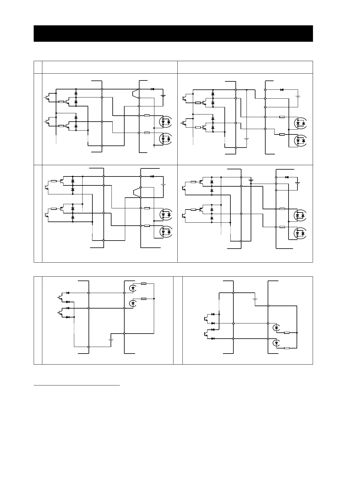
(4) Connecting a programmable controller to intelligent input terminals
When using the internal interface power supply
When using an external power supply
(Remove the jumper from the control circuit terminal block.)
(5) Connecting a programmable controller to intelligent output terminals
2.2.4 Wiring of the digital operator
- You can operate the inverter with not only the digital operator mounted in the inverter as standard equipment but
also an optional digital operator (OPE-S, OPE-SR, WOP).
- When you intend to remove the standard digital operator from the inverter and use it as remote equipment, request
your local Hitachi Distributor to supply a connection cable, ICS-1 (1-meter cable) or ICS-3 (3-meter cable). If you
prepare the cable by yourself, the following product is recommended:
HUTP5 PC 4P -X-X: Straight cable equipped with connector at both ends (made by Hitachi Metal, Ltd.)
- The length of the connection cable must be 3 m or less. If a cable over 3 m is used, the inverter may malfunction.
Output module
(EH-YT**,etc.)
Output module
(EH-YTP**,etc.)
Output module
(EH-YTP**,etc.)
Output module
(EH-YT**,etc.)
Input module
(EH-XD**,etc.)
Input module
(EH-XD**,etc.)

 Loading...


