– –
18
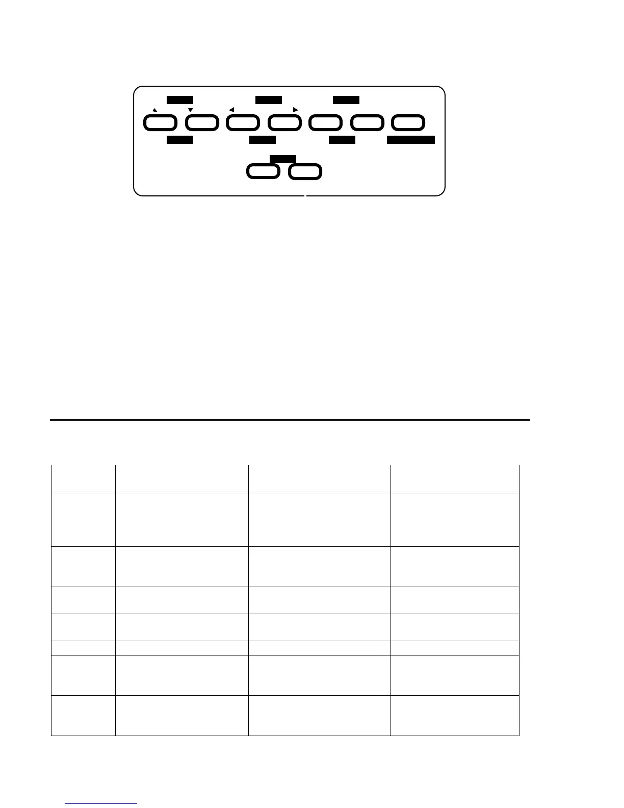
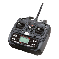
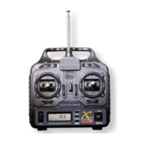
Transmitter Input Buttons:
Engine
Left Right Increase Decrease ClearDown Up
Lock Cut
DataCursor
Timer Save Active/InhibitDisplay
Edit
1122334
56
The buttons are used for different things as follows:
1. The
Edit/Display Up & Down
buttons allow you to move up and down within the model menus,
and move within the regular display.
2. The
Cursor Left/Right
buttons allow you to select options within a particular function, and
control the timer function.
3. The
Data +Increase & –Decrease
buttons allow you to increase or decrease the numerical
settings for a function.
4. The
Clear Active/Inhibit
button resets numbers and turns functions on and off.
5. The
Engine Lock
button holds the throttle channel while other channels may respond to the
transmitter.
6. The
Engine Cut
button closes the throttle so that you can kill the engine without touching the
trim lever
You’ll learn how to use these buttons in the setup sections that follow.
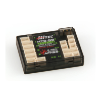
Receiver — Servo Connection List
The table below shows the hookups that should be used for each of the model types.
Note that some functions shown will not operate until they are activated in the transmitter.
Receiver
channel
Aircraft
(ACRO)
Glider
(GLID)
Helicopter
(HELI)
1
aileron
or right aileron
or right flaperon (
FLPN
)
or right elevon (
ELVN
)
right aileron
(or rudder for rudder-
elevator models)
aileron
or swash servo 1 (120’)
or swash servo 1 (180’)
2
Elevator
or V-tail right side (
VTAL
)
or left elevon (
ELVN
)
elevator or
V-tail right side (
VTAL
)
elevator
or swash servo 2 (180’)
3
throttle spoiler, throttle (on-off
controlled by
Gear
switch)
throttle
4
rudder or
V-tail left side (
VTAL
)
rudder or
V-tail left side (
VTAL
)
rudder
5
landing gear left aileron gyro sensitivity
6
flap (controlled by
VR1
)
or left flaperon (
FLPN
)
or left aileron
right flap (
4WNG
)
or single flap (
2WNG
)
pitch
or swash servo 2 (120’)
or swash servo 3 (180’)
7
optional, controlled by
VR2
left flap (
4WNG
)
or proportional channel,
controlled by
VR2
(
2WNG
)
optional, controlled by
Gear
switch