36
Lubrication
Assembly instructions
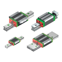
Linear Guideways
GW-04-0-EN-1910-MA
Block type Thread Thread
length
Grease nipple
1)
and recommended adapter for grease gun (A)
2)
Standard Optional
Square block A Flange block A Square/flange
block
A
HG 15
EG 15
RG 15, 20
M4 4.5 20-000272 2 20-000272 3 20-000325 4
HG 20, 25, 30, 35
QH 20, 25, 30
EG 30, 35
QE 25, 30, 35
CG 25, 30, 35
WE 21, 27, 35
QW 21, 27, 35
RG 25
QR 25
M6 × 0.75 6 20-000273 1 20-000273 2 20-000283 4
HG 45, 55, 65
QH 45
RG 45, 55, 65
QR 45
⅛ PT 10 20-000280 1 20-000280 1 On request —
QH, QE 15,
QR 20
M4 4.5 20-000272 2 20-000272 2 20-000325 4
QH 35
RG 30, 35
QR 30, 35
M6 × 0.75 6 20-000273 1 20-000273 1 20-000283 4
EG 20, 25
QE 20
M6 × 0.75 6 20-000273 1 20-000283 4 — —
CG 20
WE 17
QW 17
M3 4.5 20-000275 2 20-000275 3 5-000061 4
WE 50 ⅛ PT 10.0 20-000280 1 20-000280 2 On request —
1)
See Section 8.3.4
2)
See Section 8.9
Table 8.1 Lubrication hole on the side – Dimensions and grease nipple
For side lubrication use straight conical or ball grease nipples. In flange blocks we recommend the use the re-
spective HIWIN lubrication adapter (see Table 8.1), because of the reduced distance between flange and grease
nipple. Alternatively, funnel type grease nipples can also be used.
When the first wall is broken, do not push any further, otherwise a breakthrough into the deflection system of
the rolling elements occurs.
When using the side lubrication connection, it should not be fitted on the reference side but rather on the op-
posite side. If it should be necessary to install the lubrication connection on the reference side, make sure that
the lubrication connection does not protrude beyond the reference edge of the block. Open side lubrication holes
can be closed with a screw plug if necessary.
Diameter of the metal spike:
| Diameter 2.5 mm up to size 35
| Diameter 3.0 mm from size 45
 Loading...