EtherNet/IP 6-6
© 2005 HMS Industrial Networks. AB7607 User manual
Output Assembly
The output assembly contains a 32-bit run/idle register and a 32-bit command reg-
ister followed by the data in the Anybus-X’s output data table.
The output data format and content is determined by the DeviceNet scanner con-
figuration. The data appears in the table as it is mapped to the DeviceNet output
connections. The output data in the assembly is 500 bytes long; however, only the
size configured for the output data table will be used, the remaining space will be
ignored.
Note: EtherNet/IP I/O connections append a 32-bit Run/Idle register at the front
of the output data. The actual output data transferred in the I/O connection
includes this extra 4 bytes at the front of the output assembly described above.
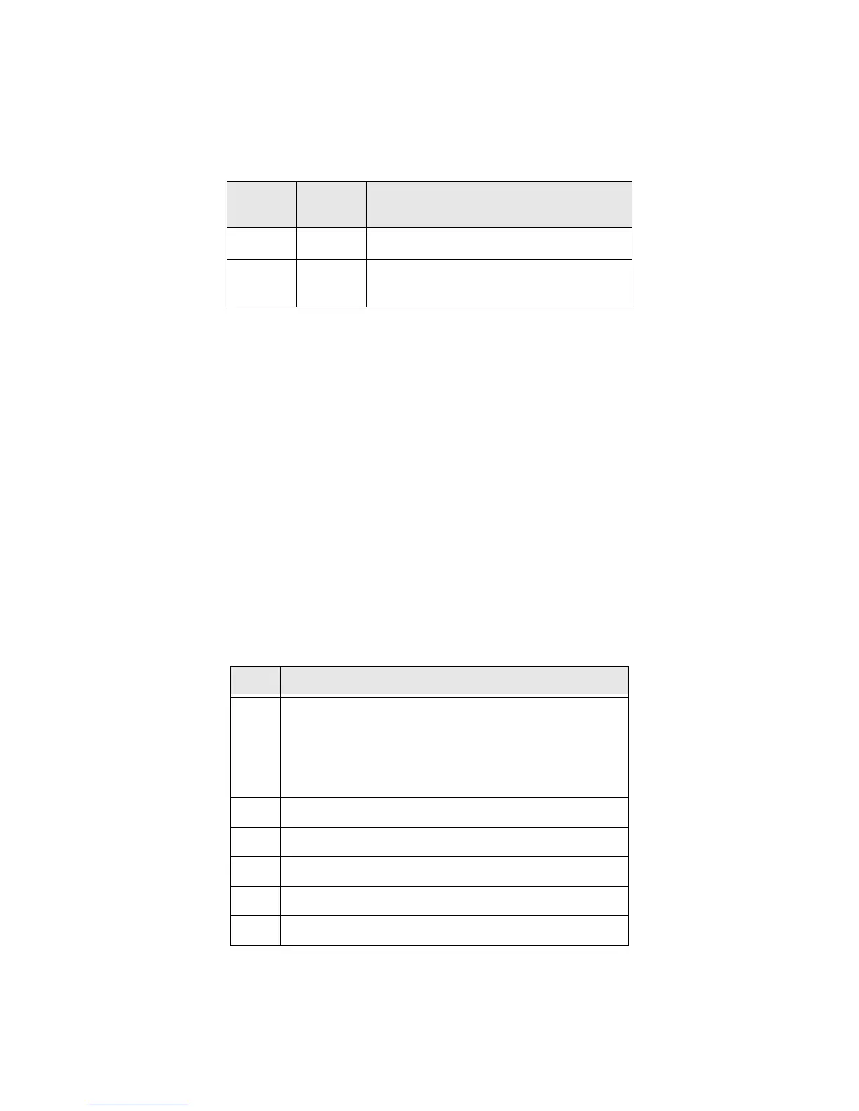
The Command register is a bit string with the following bit definitions.
Byte
Offset
Size
in Bytes
Description
0 4 Run/Idle register.
4Up to
500
Output data.
Table 6-5 Output Assembly Format
Bit Description
0 Local Run Mode. Used in conjunction with the Sys-
tem Run Mode bit in the Command register to deter-
mine the run mode of the Anybus-X. Both bits must
be set for the Anybus-X to be in Run mode; otherwise
the module will be in Idle mode.
1 Fault. Sets a fault condition in the Anybus-X.
2 Disable DeviceNet network.
3 Not used.
4 Reset the Anybus-X module.
5-31 Not used.
Table 6-6 Output Command Register Bit Definitions