Module Description 1-6
© 2005 HMS Industrial Networks AB7607 User manual
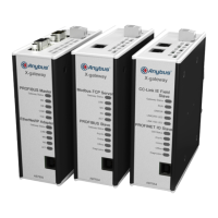
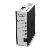
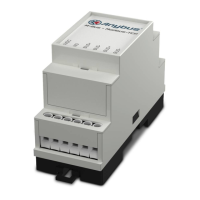
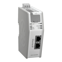
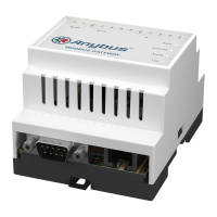
Hardware Description
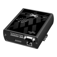
All connections, whether power or fieldbus, to the Anybus-X are made on one end
of the module. Phoenix connectors are provided for power and DeviceNet connec-
tions. A RJ-style connector is provided for Ethernet connection. There is a 9-pin
D-Subminiature connector for the auxiliary RS-232 port that is used for field firm-
ware upgrades. See “Installation” on page 2-1 for more details on the connectors.
There is an 8 position dip switch on the end of the module that can be used to
select a portion of a default IP address that may be used to permit an intranet con-
nection. See “Starting the Tool” on page 3-2 for more details on configuring the IP
address using the switches.
On the front of the Anybus-X module are 7 LEDs that are used for status indica-
tion. These LEDs provide visual status for the overall module, the DeviceNet
interface, and the Ethernet interface. See “Anybus-X LEDs” on page 10-1 for
details on how the LEDs are used.
The back of the module has a DIN rail mount to allow the module to be mounted
on a DIN rail.