TM-258 267 Page 39
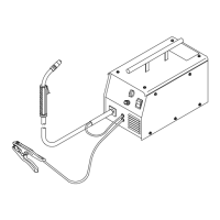
Handler 140
Description
Part
No.
Dia.
Mkgs.
Item
No.
Figure 10-1. Main Assembly
Quantity
1 199 566 Door, Access 1... ................ .. ......................................................
2 196 006 Hinge, Door 2... ................ .. .......................................................
3 211 887 Hub, Nut 1... ................ .. .........................................................
4 204 608 Nut 1... ................ .. ..............................................................
5 202 998 Spring, CPRSN 1... ................ .. ...................................................
6 203 072 Washer, Flat 1... ................ .. ......................................................
7 211 339 Hub, Spool 1... ................ .. .......................................................
8 202 726 Adapter, Spool Hub 1... ................ .. ................................................
9 PC1 256 985 Circuit Card Assy, Control 1... ...... ..... .. ...........................................
10 195 999 Base, Lower 1... ............... .. ......................................................
11 CB1 210 109 Supplementary Protector, 25 Amp 1... ..... ..... .. ...................................
12 196 467 Tubing, PVC .187 ID x .312 OD x 23.00 1... ............... .. ...............................
13 GS1 216 397 Valve, Gas 1... ..... ..... .. ........................................................
14 197 198 Cable Tie, .700-.799 Bundle Dia 2... ............... .. .....................................
15 147 545 Cord Set, 125v 5−15P 14ga 3/C 7ft SPT−3 JKT 1... ............... .. ........................
16 111 443 Bushing, Strain Relief 1... ................ .. ..............................................
17 137 761 Nut, Gas Valve 1... ............... .. ....................................................
18 FM 196 063 Motor, Fan 1... ..... ..... .. ........................................................
19 409 953-001 Blade, Fan Cooling 1... ........... .. ................................................
20 T1 257 984 Transformer, Power Assy 1... ...... ...... .. ...........................................
21 208 015 Handle, Carrying 1... ............... .. ..................................................
22 +196 005 Wrapper 1... .............. .. ..........................................................
23 204 036 Label, Warning 1... ............... .. ....................................................
24 203 491 Clamp, Capacitor 1... ............... .. ..................................................
25 C1 193 039 Capacitor, Electlt 53000uf 1... ..... ..... .. ...........................................
26 Z1 203 868 Reactor Assy 1... ...... ...... .. .....................................................
27 SR1 193 191 Rectifier Assy 1... ..... ..... .. .....................................................
28 193 193 Bus Bar (Positive) 1... ............... .. .................................................
29 217 831 Baffle, Center 1... ............... .. .....................................................
30 405 576-001 Bushing, Terminal 1... ........... .. .................................................
31 193 144 Insulator, Output Stud 1... ............... .. ..............................................
32 193 194 Bus Bar (Negative) 1... ............... .. ................................................
33 216 830 Label, Warning 1... ............... .. ....................................................
34 134 201 Stand-Off 4... ............... .. .........................................................
35 S2 257 585 Switch, Rotary 1... ...... ...... .. ....................................................
36 R2 209 873 Potentiometer, 1... ..... ..... .. ....................................................
37 258 234 Panel, Front W/Nameplate 1... ............... .. ..........................................
38 257 796 Clamp, Work 1... ............... .. ......................................................
39 196 619 Cable, Work 1... ............... .. ......................................................
40 S1 196 575 Switch, Rocker SPST 1... ...... ...... .. ..............................................
41 207 079 Knob, Pointer (Voltage) 1... ............... .. .............................................
42 211 338 Knob, Pointer (Wfs) 1... ............... .. ................................................
43 DM 257 097 Wire Feeder Assy 1... ..... ..... .. .................................................
44 CR3 217 584 Contactor 1... ..... ..... .. .........................................................
45 PL1 230 033 LED 1... ..... ..... .. .............................................................
46 258 069 Label, Weld Guide 1... ............... .. .................................................
46 258 438 Label, Weld Guide (French) 1... ............... .. .........................................
47 204 711 Latch 1... ............... .. ............................................................
48 203 572 Label, Warn Gen Precaution (En/Fr Models Only) 1... ............... .. ......................
49 Label, Nameplate (Order By Model And Serial Number) 1... .......................... .................
+When ordering a component originally displaying a precautionary label, the label should also be ordered.
To maintain the factory original performance of your equipment, use only Manufacturer’s Suggested
Replacement Parts. Model and serial number required when ordering parts from your local distributor.