Discovery QDR Series Technical Manual
8-3
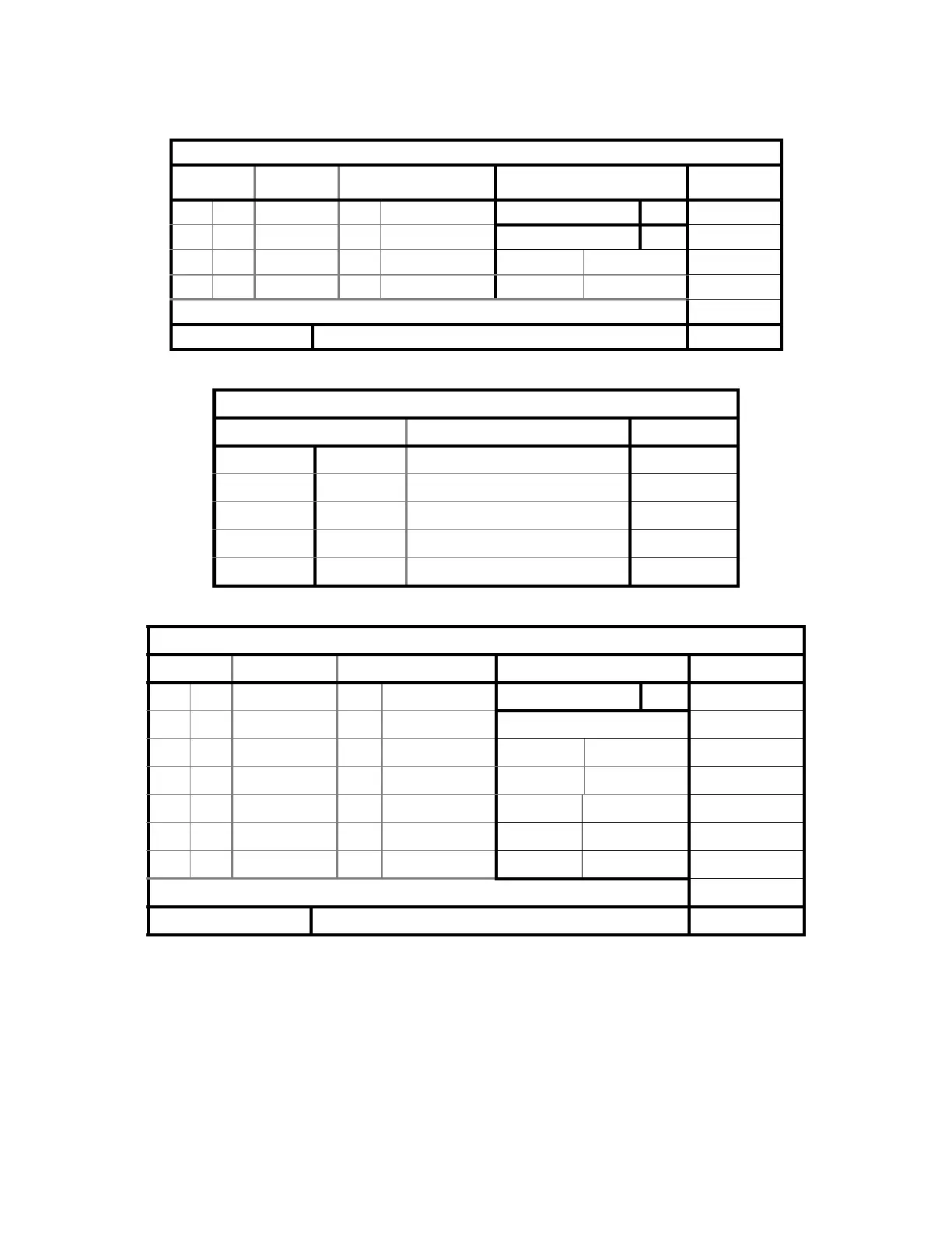
128-Channel Detector Assembly (C, W and SL Models only)
LED’s Voltage Voltage Source Jumpers Refer to...
D4 On +12VDC Int. Voltage Reg. J1 (Run/Test) In
D5 On -12VDC Int. Voltage Reg. J2 (Run/Test) In
D6 On VCC Int. Voltage Reg.
D7 On +5VDC Int. Voltage Reg.
U14 (LED display) Flickers “1” on bootup, then lock on “2”.
Potentiometer R18 (A/D GAIN CNTRL) See procedure in Section 4. Page 4-26
Detector Array Assembly (A Model only)
Source Source Refer To...
+15VDC Ext. ADC PCB
-15VDC Ext. ADC PCB Figure 5-8
+5VDC Ext. ADC PCB
+12VDC Int. Voltage Reg.
-12VDC Int. Voltage Reg.
ADC (A Model only)
LEDs Voltage Voltage Source Jumpers Refer to...
D1 On VCC Int. Voltage Reg. JP3 (GROUND) Out
D2 On +5VDC Int. Voltage Reg. JP5 (HI/LO RES)
D3 On +12VDC Int. Voltage Reg. A In
D4 On -12VDC Int. Voltage Reg. Figure 5-11
D5 On -5VDC Int. Voltage Reg.
- - +7VDC Ext C-Arm Int. Bd.
- - +/-15VDC Ext C-Arm Int. Bd.
U14 (LED display) Flickers “1” on bootup, then lock on “2”.
Potentiometer P3 (A/D GAIN CNTRL) See procedure in Section 4. Page 4-26