BF15D-BF20D
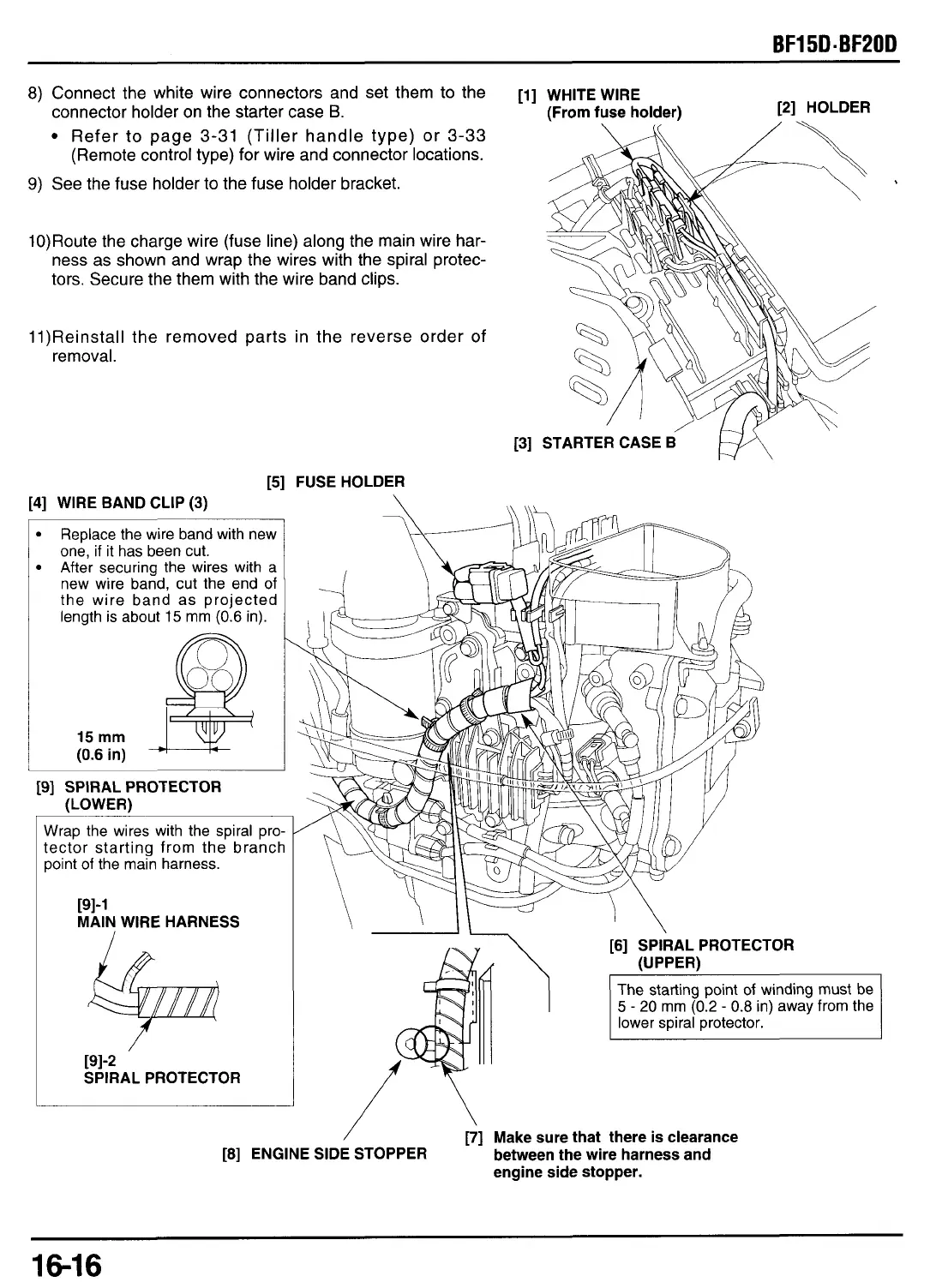
8)
Connect the white wire connectors and set them to the
connector holder on the starter case
B.
Refer
to
page 3-31 (Tiller handle type) or 3-33
(Remote control type) for wire and connector locations.
9)
See the fuse holder to the fuse holder bracket.
10)Route the charge wire (fuse line) along the main wire har-
ness as shown and wrap the wires with the spiral protec-
tors. Secure the them with the wire band clips.
11)Reinstall the removed parts in the reverse order of
removal.
[5] FUSE HOLDER
[4]
WIRE BAND CLIP (3)
\
Replace the wire band with new
one, if it has been cut.
After securing the wires with a
new wire band, cut the end of
the wire band as projected
length is about
15
mm
(0.6
in).
15
mm
j
(0.6 in)
-+---+-
I
191
SPIRAL PROTECTOR
(LOWER)
~
Urap the wires with the spiral pro-
:ector starting from the branch
Doint of the main harness.
191-1
MAIN WIRE HARNESS
191-2
SPIRAL PROTECTOR
[l]
WHITE WIRE
fFrom fuse holder)
[2]
HOLDER
\
[6] SPIRAL PROTECTOR
(UPPER)
5
-
20
mm
(0.2
-
0.8
in) away from the
lower spiral protector.
/
[7]
Make sure that there is clearance
engine side stopper.
[8] ENGINE SIDE STOPPER
between the wire harness and
1646












 To Next Page