BF15DmBF20D
9)
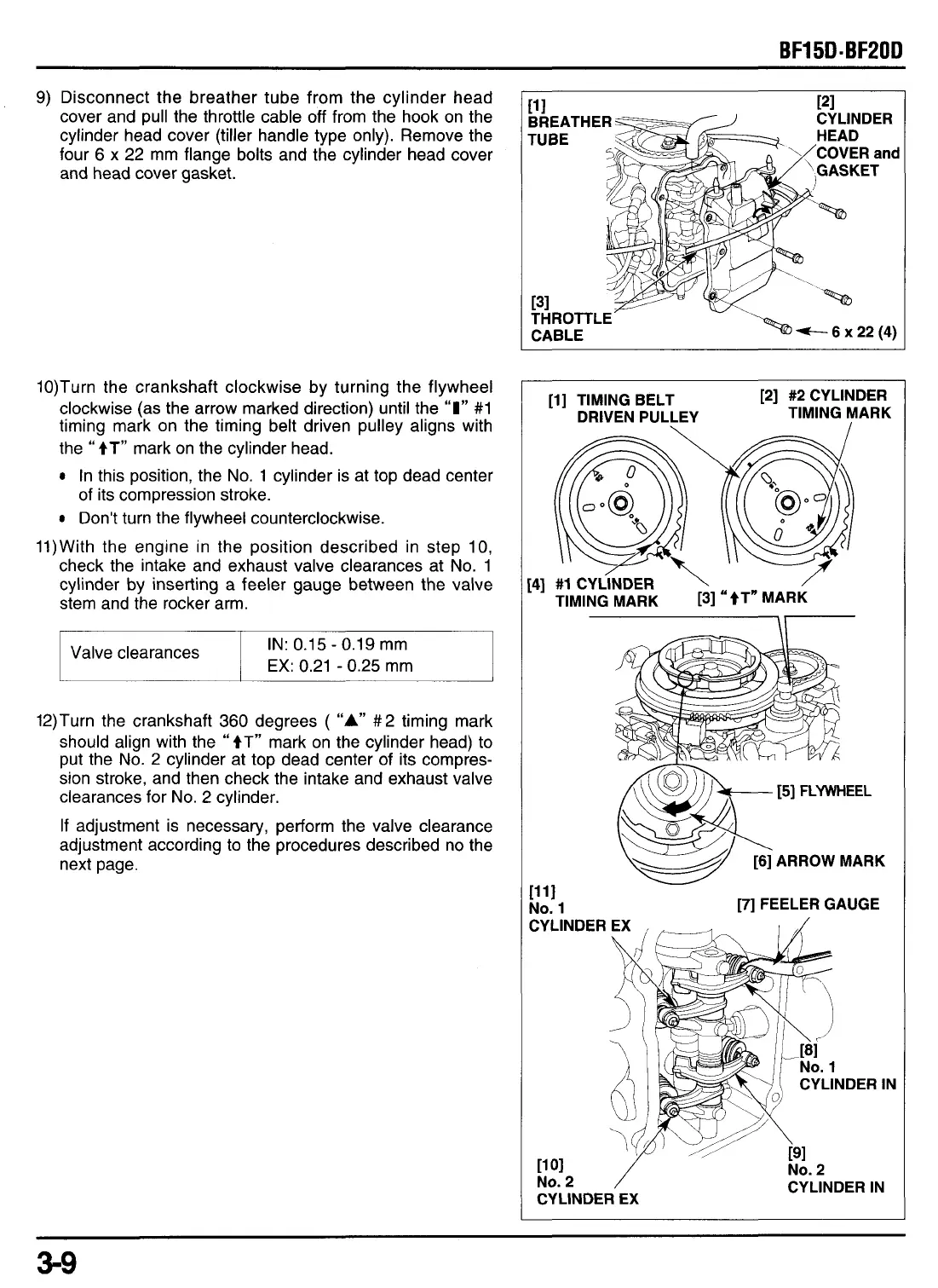
Disconnect the breather tube from the cylinder head
cover and pull the throttle cable
off
from the hook on the
cylinder head cover (tiller handle type only). Remove the
four 6 x 22 mm flange bolts and the cylinder head cover
and head cover gasket.
10)Turn the crankshaft clockwise by turning the flywheel
clockwise (as the arrow marked direction) until the
“I”
#1
timing mark on the timing belt driven pulley aligns with
the
“
tT”
mark on the cylinder head.
In this position, the
No.
1
cylinder is at top dead center
of
its compression stroke.
Don’t turn the flywheel counterclockwise.
With the engine in the position described in step 10,
check the intake and exhaust valve clearances at
No.
1
cylinder by inserting a feeler gauge between the valve
stem and the rocker arm.
11
IN:
0.1
5 -0.1
9
mm
EX:
0.21
-
0.25
mm
Valve clearances
12)Turn the crankshaft
360
degrees
(
“A”
#2 timing mark
should align with the
“
tT”
mark on the cylinder head)
to
put the
No.
2
cylinder at top dead center of its compres-
sion stroke, and then check the intake and exhaust valve
clearances for
No.
2 cylinder.
If adjustment is necessary, perform the valve clearance
adjustment according to the procedures described no the
next page.
[l] TIMING BELT
[2] #2 CYLINDER
DRIVEN PULLEY TIMING MARK
3-9