vi UDC3300 Basic Model: DC33XB User Manual 12/00
Figures
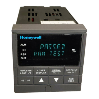
Figure 1-1 Operator Interface Displays and Indicators _______________________________1
Figure 2-1 Dimensions________________________________________________________3
Figure 2-2 Mounting Method ___________________________________________________4
Figure 2-3 Composite Wiring Diagram ___________________________________________6
Figure 2-4 Line Voltage Wiring _________________________________________________7
Figure 2-5 Input #1/#2 Connections______________________________________________8
Figure 2-6 Electromechanical Relay Output – Model DC330X-EE-XXX __________________9
Figure 2-7 Solid State (SS) Relay Output — Model DC33X-AA-XX ____________________10
Figure 2-8 10-amp SS External Relay Output — Model DC330X-SS-XX ________________10
Figure 2-9 Open Collector Output — Model DC330X-TT-XXX ________________________11
Figure 2-10 Current Output Current/Time Duplex, Time/Current Duplex, Position
Proportional or Three Position Step Control ____________________________12
Figure 2-11 Auxiliary Output and Three-Relay Output_______________________________12
Figure 2-12 Position Proportional Output or Three Position Step—Models
DC330X-EE-XXX-X2, DC330X-AA-XXX-X2 ____________________________13
Figure 2-13 Auxiliary Output Connections— Models DC330X-XX-2XX,
DC330X-XX-5XX _________________________________________________14
Figure 2-14 Digital Inputs Connections—Model DC330X-XX-XX3 _____________________14
Figure 2-15 RS422/485/ASCII or Modbus Communications Option Connections__________15
Figure 2-16 Transmitter Power for 4-20 mA 2-wire Transmitter Using Open Collector
Alarm 2 Output—Model DC330X-XT-XXX _____________________________16
Figure 2-17 Transmitter Power for 4-20 mA 2-wire Transmitter Using Auxiliary
Output—Model DC330X-XX-2XX or DC330X-XX-5XX ____________________16
Figure 3-1 Prompt Hierarchy __________________________________________________19
Figure 5-1 Ramp/Soak Profile Example__________________________________________58
Figure 5-2 Program Record Sheet______________________________________________59
 Loading...
