Excel 800 Description of the I/O Modules
53 EN1B-0375GE51 R0910
Terminals
74 78
73 77
72
76
71
75
24
V
~
24
V
~
24
V
~
0
24
V
~
0
COM
B
COM
B
COM
A
COM
A
13 4323 5333 63
12 4222 5232 62
NO NONO NONO NO
NC NCNC NCNC NC
COM COMCOM COMCOM COM
11 4121 5131 61
RELAY BLOCK 1 RELAY BLOCK 2
25
CROSS CONNECTOR (REMOVABLE)
Fig. 77 Terminal assignment and internal connections of
relay output modules
Terminal Signal Comment
71, 75
COM a
2-wire communication bus
(LON/Panel Bus)
72, 76
COM b
2-wire communication bus
(LON/Panel Bus)
73, 77
24 V~
Power supply
74, 78
24 V~0
Power supply
11
REL1 N.O.
Relay 1 N.O. contact
12
REL1 N.C.
Relay 1 N.C. contact
13
R1 COM
relay 1 common contact
21
REL2 N.O.
Relay 2 N.O. contact
22
REL2 N.C.
Relay 2 N.C. contact
23
R2 COM
Relay 2 common contact
31
REL3 N.O.
Relay 3 N.O. contact
32
REL3 N.C.
Relay 3 N.C. contact
RELAY BLOCK 1
33
R3 COM
Relay 3 common contact
41
REL4 N.O.
Relay 4 N.O. contact
42
REL4 N.C.
Relay 4 N.C. contact
43
R4 COM
Relay 4 common contact
51
REL5 N.O.
Relay 5 N.O. contact
52
REL5 N.C.
Relay 5 N.C. contact
53
R5 COM
Relay 5 common contact
61
REL6 N.O.
Relay 6 N.O. contact
62
REL6 N.C.
Relay 6 N.C. contact
RELAY BLOCK 2
63
R6 COM
Relay 6 common contact
25
Shield connection (functional earth),
internally connected to the DIN rail
Table 54 Description of relay output module terminals
Permissible Loads
Max. load Min. load
Per relay
output
module (total)
19…250 VAC
current at cos φ ≥ 0.6: 12 A
1…29 VDC
12 A resistive, 3 A inductive
–
Per normally
open contact
19…250 VAC
current at cos φ ≥ 0.6: 4 A
1…29 VDC
4 A resistive, 1 A inductive
50 mW
Per normally
closed
contact
19…250 VAC
current at cos φ ≥ 0.95: 2 A,
current at cos φ ≥ 0.6: 1 A
1…29 VDC
4 A resistive, 1 A inductive
50 mW
Table 55 Permissible loads of relay output modules
Notes
In the case of voltages above 30 VAC/DC and if inductive
components are to be connected to relays switching
more often than once every 2 minutes, these com-
ponents must be prevented from causing harmful
interference to radio or television reception (conformance
with EN 55014).
Max. voltage for UL 864-compliant applications is 24 V.
Status LED Behavior
Relay output
Mode LED
N.O.*
(direct)
N.C.*
(reverse)
Automatic mode, logical
state “ON”
ON ON OFF
Automatic mode, logical
state “OFF”
OFF OFF ON
Override mode (setting “0”) Flashes OFF ON
Override mode (setting “1”) Flashes ON OFF
*As configured using CARE.
Table 56 Relay output status LED behavior
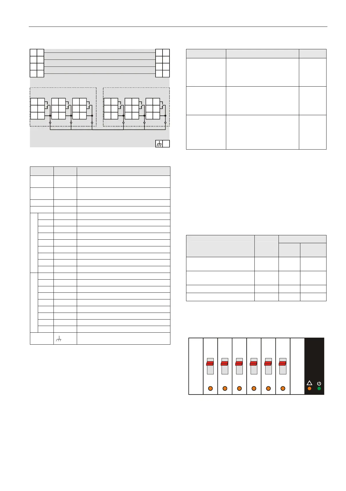
Status LEDs with Manual Overrides
12
3
4
5
6
Honeywell
--1
--0
--AUTO
!
Fig. 78 Manual overrides (toggle switches)
The …R824 Relay Output Modules are equipped with
manual overrides: one for each relay output. These toggle
switches can be manually set to either "AUTO" or "0" or "1".
 Loading...