107026-11-EN FR26 ROW 302 Printed in France 13
Notes:
1/ For Vdc versions, the supply connection is the
following: terminal (1): +
terminal (2): -
However, the FF-SB14 is protected against reversed
polarity thanks to a rectifier.
2/ In order to get the specified immunity to electrical
noise, the earth terminal must be connected to the
main earth of the machine.
3/ Additional protection fuse on the power line:
- 500 mA (for 120 Vac mains) or 400 mA (for 240 Vac
mains) on both emitter and receiver:
500 mA (for 24 Vdc mains) on both emitter and
receiver.
4.2.5 Machine stop control
Relays X1 and X2 are switched simultaneously. An
internal permanent check ensures that both relays
have the same status. If one of the two contacts X1 or
X2 becomes accidently welded, the remaining contact
would no longer be able to close.
It is therefore
important to use the two signals to prevent
operation of the machine.
Protection of relays contacts
Warning:
inductive loads will generate high voltage
transients which will degrade the life expectancy of the
relay contacts.
The delivered RC components (220 Ω + 0,22 µF) will
avoid this problem and will allow the guarantee to
apply.
Important: safety norms require that these RC
components are connected in parallel with the load
(see schematics).
Note: these RC components can be replaced by
varistors for Vdc interfaces.
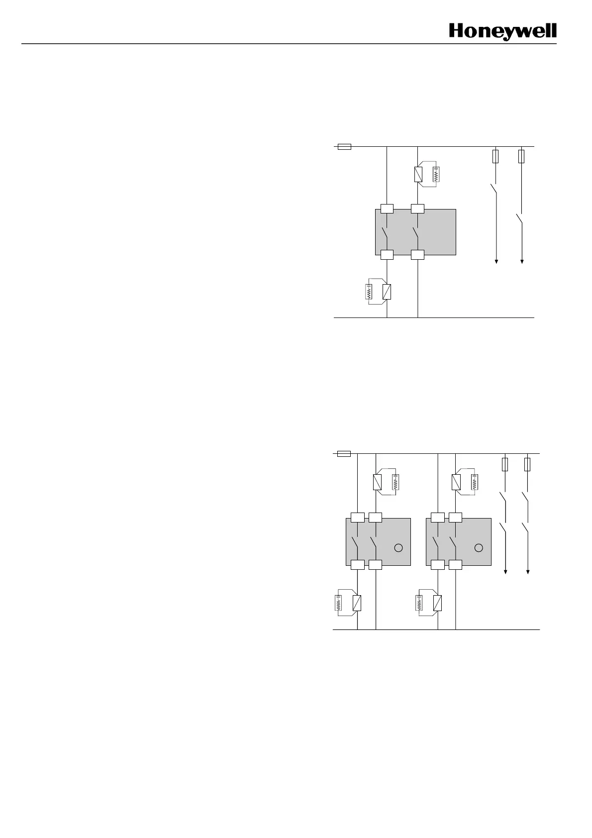
Machines with double stopping circuitry
In this case, use the contacts (3) and (4) & (5) and (6)
separately:
Machine
stopping
circuitry
FF-SB14R
4
5
K2
K1
*
*
6
3
K2
K1
*RC component delivered with the unit:
220 Ω + 0.22 µF (see § 4.2.8 for correct interfacing of
K1 and K2, the partial example here being more
appropriate for ac power).
Connection of grouped barriers
4 relays K1, K2, K3 and K4 would be used in the
following manner:
FF-SB14R
B
4
5
K2
K1
*
*
Machine
stopping
circuitry
K4
K2
K1
K3
3
6
3
6
FF-SB14R
A
4
5
K4
K3
*
*
*RC component delivered with the unit: 220 Ω +
0,22 µF (see § 4.2.8 for correct interfacing of K1 and
K2, the partial example here being more appropriate
for ac power).
FSB14_23
FSB14_24
 Loading...