20 107026-11-EN FR26 ROW 302 Printed in France
4.3.8 Automatic restart/start & restart
interlock (available on FF-SB14R❏❏❏
❏❏❏❏❏❏
❏❏❏-
S2❏
❏❏
❏ models only)
Description of the different modes
Automatic mode
In the automatic mode, the barrier is automatically
reset at power up or after any intrusion in the
detection field
. There’s no need for pressing a push-
button for reseting the system and closing contacts
B1-B2 and C1-C2. There is no need to open the
receiver unit in this mode except if the FSD monitoring
is required (see § 8.6).
Start interlock mode
In the start interlock mode, it is necessary to press
a push-button to reset the system and close
contacts B1-B2 and C1-C2 at power up only
.
Normally closed contact of this push-button must be
connected between terminals C3 and C5. The receiver
unit must be opened to change the jumper links
position (refer to § 8.6).
Start and Restart interlock mode
In that mode, pushing a button is necessary at
power up or after any intrusion in the detection
field to reset the system and close contacts B1-
B2 and C1-C2
. Normally open contacts of this push-
button must be connected between terminals C3 and
C5. The receiver unit must be opened to change the
jumper links position (refer to § 8.6).
Selection of a restart mode
The selection of one of these modes is done with the
jumper links position (refer to § 8.6).
Automatic mode
The device is delivered in this mode. If the FSD
monitoring is required then the jumper links position
must be changed (refer to § 8.6).
C3
C5
no connection or FSD monitoring loop
Start interlock mode
Change the jumper links position (refer to § 8.6)
NC contact of a push-button must be connected
between C3 and C5
C3
C5
(NC P/B)
t > 100 ms
Start & Restart interlock mode
Change the jumper link position (refer to § 8.6)
NO contact of a push-button connected between C3
and C5
C3
C5
(NO P/B)
100 ms < t < 1 s
4.3.9 Monitoring / reset (available on
FF-SB14R❏❏❏
❏❏❏❏❏❏
❏❏❏-S2❏
❏❏
❏ models only)
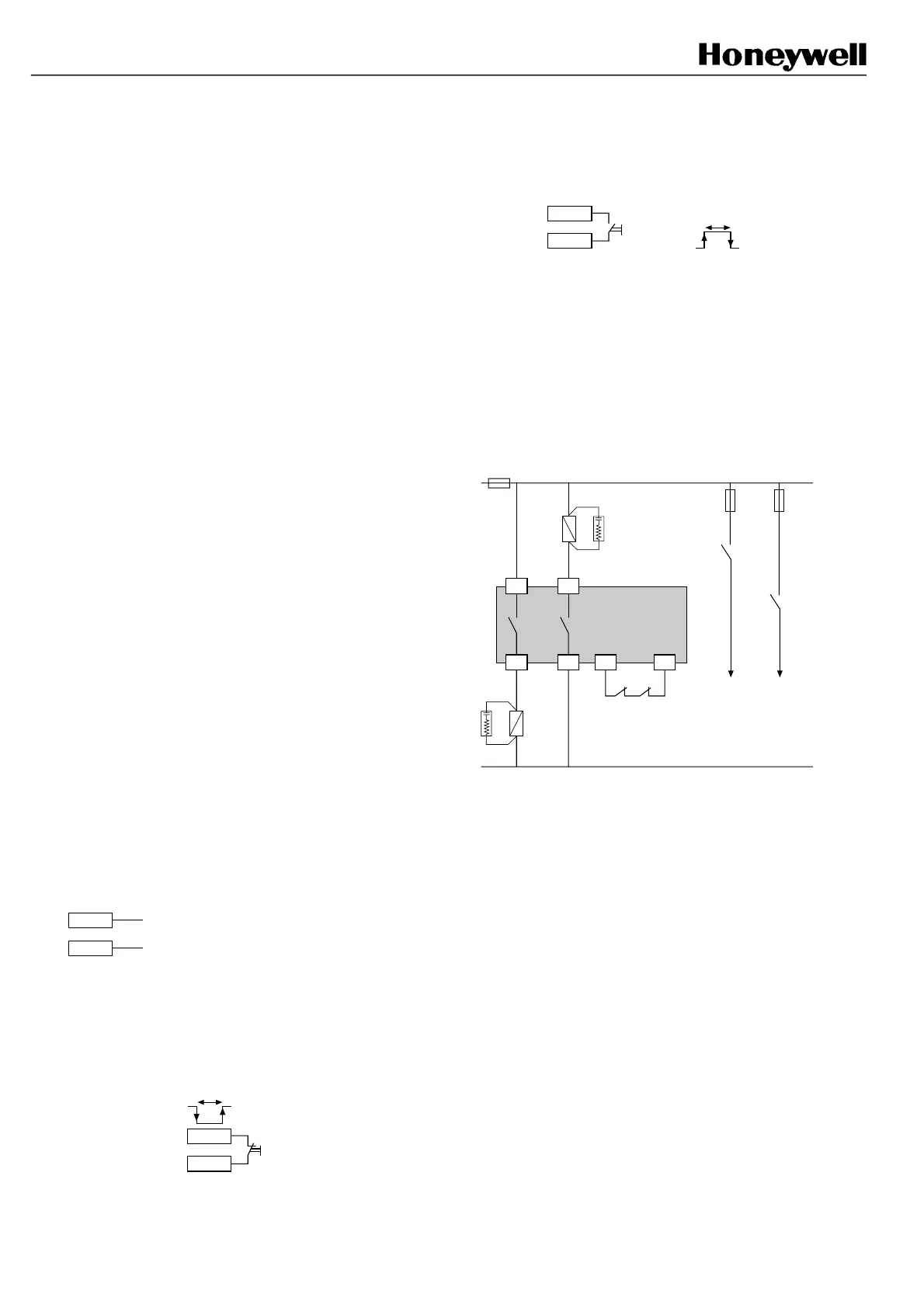
The Final Switching Device (FSD) monitoring function
can be used with either the automatic mode, the start
interlock mode or the start & restart interlock mode.
Normally closed contacts of the relays used as final
switching devices (FSD) can be wired between the
terminals C3 and C5 as shown on the following figure:
Machine
stopping
circuitry
K2
(NO)
FF-SB14R
K1
(NO)
C5B2
C1
K2
FSD
K1
FSD
B1
C2 C3
K1
(NC)
K2
(NC)
If the start interlock mode & restart interlock mode are
used, refer to § 4.3.10 for correct interfacing of K1 and
K2. The partial example here being more appropriate
for ac power.
FSB14_40
FSB14_41
FSB1❏4_42
FSB14_43
 Loading...