107026-11-EN FR26 ROW 302 Printed in France 21
4.3.10 Examples of electrical interfaces involving additional relaying
Note 1: If it is necessary to add relays between the barrier and the machine control circuitry, it would be advisable to
monitor that these relays are functioning properly. The cases described below should be considered as examples of
use of the barriers. The adjustment of the machine to the electrical circuit should be carried out with great regard for
safety (any breakdown of an additional relay should be detected automatically).
Note 2: Contacts of relays connected to the test input shall be golden plated in order to switch low currents.
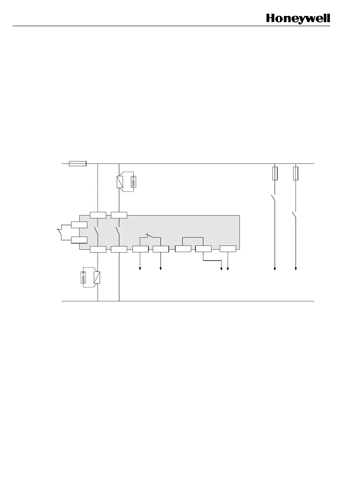
Example 1: Automatic reset without Final Switching Device monitoring
(use of example 7 is recommended)
C1 B1
B2
K2
FSD
C2
C4
C5
Test
Machine stopping
circuitry
K1
FSD
FF-SB14
Signalling
(relay status)
A3
Signalling
(beam status)
K1
K2
FSD: Final Switching Device
* 220 Ω + 0.22 µF
A1 A2
*
*
C3 C5
In this example, the reset of the safety barrier is automatically performed at power up or after any intrusion in the
detection field. However,
the additional relays are not monitored and a possible failure of both relays K1 and K2
will not be detected. If a possible failure of K1 and K2 needs to be detected, please refer
to example 2.
FSB14_44
 Loading...