107026-11-EN FR26 ROW 302 Printed in France 37
8.4 Changing output relays
Necessary tools:
• 1 TORX T20 or ACX20 screwdriver
• flot blade screwdriver (3 mm to 4 mm)
• 1 screwdriver for recessed head screws
Spare parts: see § 9.3
The output relays are located on the power supply board of
the receiver unit.
a) Unscrew the 4 screws of the cover plate that
carries the connector.
a) Remove the cover plate and the electronic board
that is fixed to it by letting the card sliding out
(fig. 8-3-1).
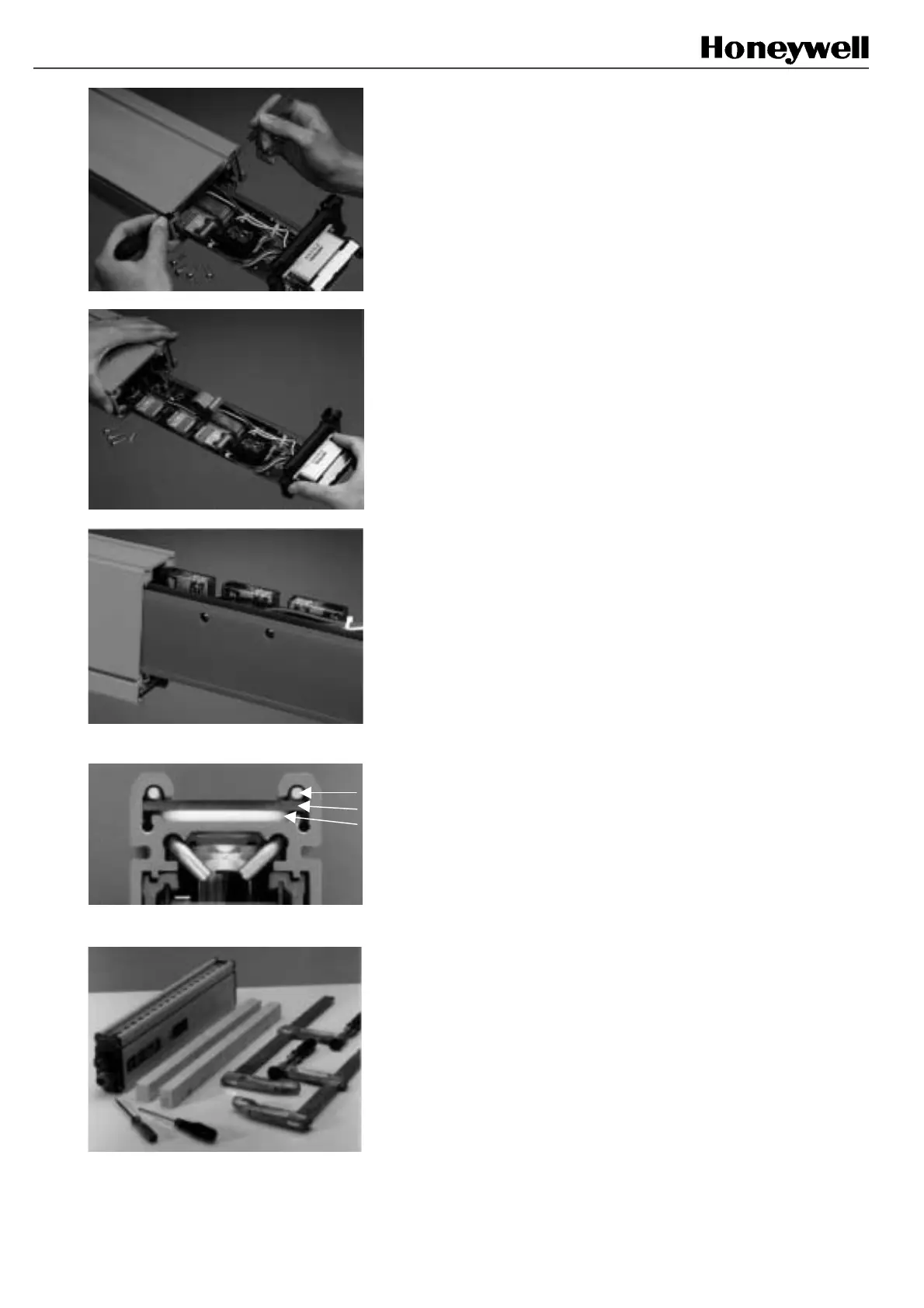
c) Disconnect the flat cable on the upper board
when possible (fig. 8-4-1).
d) Continue to remove the card from the case until the
3 output relays are exposed (fig. 8-4-2).
e) Screw off the relay board from the power supply
board (2 holes drilled through the orange rail ease
access to the screws) (fig. 8-4-3).
f) Carefully disconnect the relay board.
g) Replace the relay board by a new one of the
same reference; the position of the connectors
should be identical to the previous mounting.
Note: The 3 output relays must be replaced at the same
time. Although the procedure is easy, it must be carried out
by qualified people.
8.5 Changing a transparent front
plate
Necessary tools (see fig 8-5-2)
• TORX T20 or ACX 20 screw driver
• 2 to 4 joiner clamps (2 for a SB14 400 mm,
4 for FF-SB14 1000 mm)
• 2 wooden battens (section 30 x 30 mm for
example).
Spare parts: Transparent front plates delivered with
gasket (see § 9.3)
a) Unscrew the 4 screws of each of the 2 end
covers and remove them. Remove the cover plate
and the electronic board entirely (refer § 8.4 and
fig. 8-5-3).
Fig 8-4-1
Fig 8-4-2
Fig 8-4-3
(1) Pressing rods
(2) Front plate
(3) Gasket
Fig 8-5-1
Fig 8-5-2
 Loading...