107026-11-EN FR26 ROW 302 Printed in France 15
4.2.8 Example of electrical interface involving additional relaying
Note: If it is necessary to add relays between the barrier and the machine control circuitry, it would be advisable to
monitor that these relays are functioning properly. The case described below should be considered as an example of
use of the barriers. The adjustment of the machine to the electrical circuit should be carried out with great regard for
safety (any breakdown of an additional relay should be detected automatically).
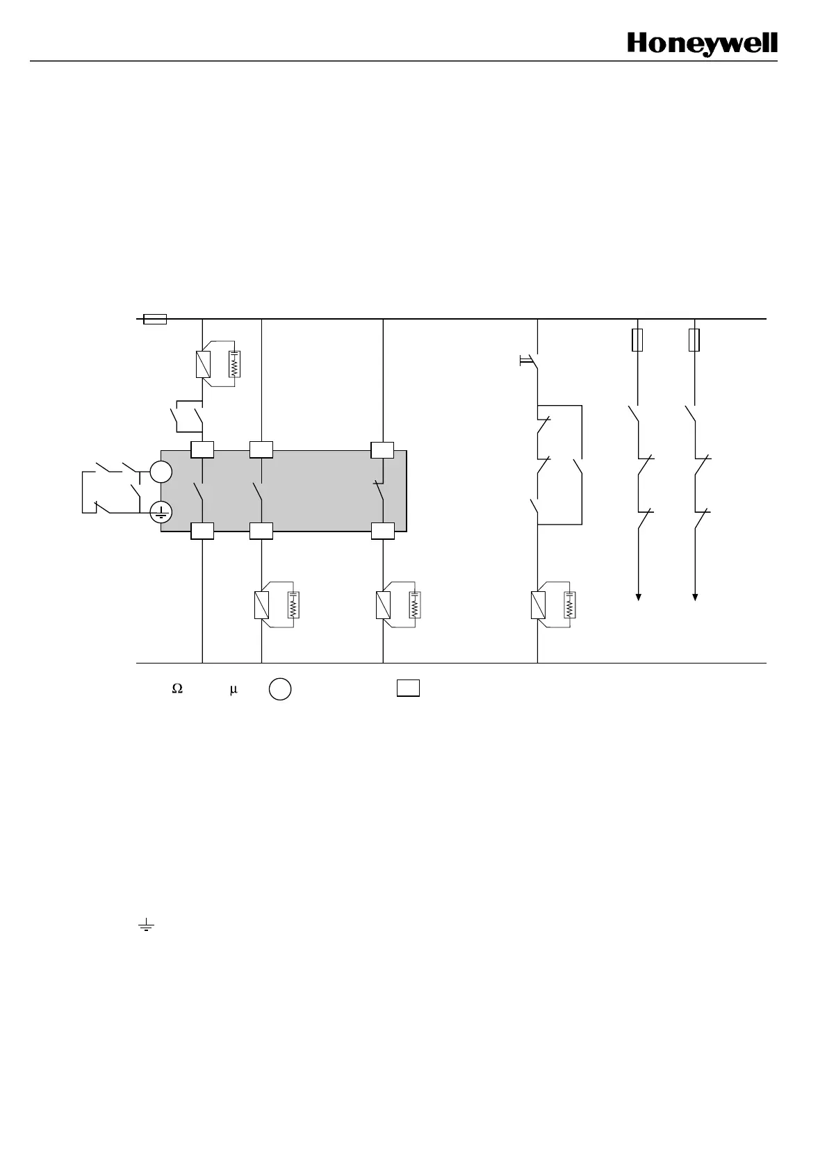
Example 1: Start & restart interlock and Final Switching Device (FSD) monitoring
performed by an additional relay circuitry (use of example 2 is strongly recommended)
FF-SB14R
4
K1
K2
5
6
K1K2
K3
K4
FSD
FSD
*
*
* 220 + 0.22 F : supply plug : signal plug
3
3
3
1
2
K3
3
K1
K4
Machine stopping
circuitry
K1
K3
K4
K2
K3
K4
K4
K4
K1
K2
K3
Start P/B
*
At power up, the FF-SB14 barrier is in test mode since no contact between terminal (3) and Earth is established. K3 is
energized through NC contacts. To reset the barrier, the ”Start push-button” must be pressed which energizes the
relay coil K4. Connection between (3) and Earth is then established which enables relay coils K1 and K2 to be
energized and relay coil K3 to be de-energized. NO contacts of K1, K2 relays go to the ON state while NC contacts of
K3 and K4 go to the ON state to enable the activation of a machine cycle. If one of the FSD (K1 and K2) contacts
remains accidently closed, pressing the start push-button will have no effect and the safety function will be
maintained. All external relays are safety relays.
Notes:
1.
If NC contacts of K4 remain closed, then the NO contact of K4 remains open between terminals (3)
and
and the light curtain remains in alarm even if the start push-button P/B is pressed.
2. Contacts of relays connected to the test input shall be golden plated in order to switch low currents.
FSB14_29
 Loading...