28 107026-11-EN FR26 ROW 302 Printed in France
5. Setting up
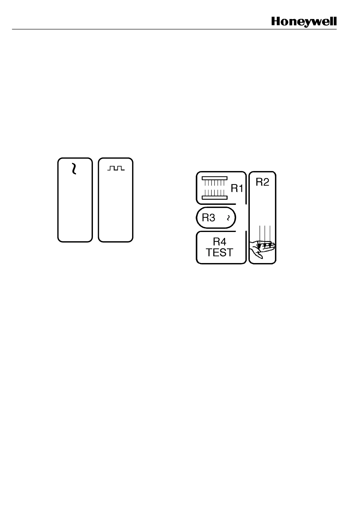
5.1 Front panel indicators
• Emitter
E1: yellow indicator
Power on indicator
E2: yellow indicator
Synchronisation beam reception indicator
Lights on if the synchronisation beam is established
Note: E2 normally lights on if the occultation occurs
near the emitter
E2E1
• Receiver
R1: red indicator. Normally OFF. Flickers when
reception level is too low. Lits on during test or during
a beam interruption near the receiver, or in case of
important misalignment.
R2: red indicator. Lits on when relays are de-
energized.
R3: green indicator. Lits on when relays are energized
R4: yellow indicator. Normally OFF.
Test input implementation. Lits during test and flickers
if the system needs to be reset.
FSB14_51
FSB14_52
 Loading...