107026-11-EN FR26 ROW 302 Printed in France 27
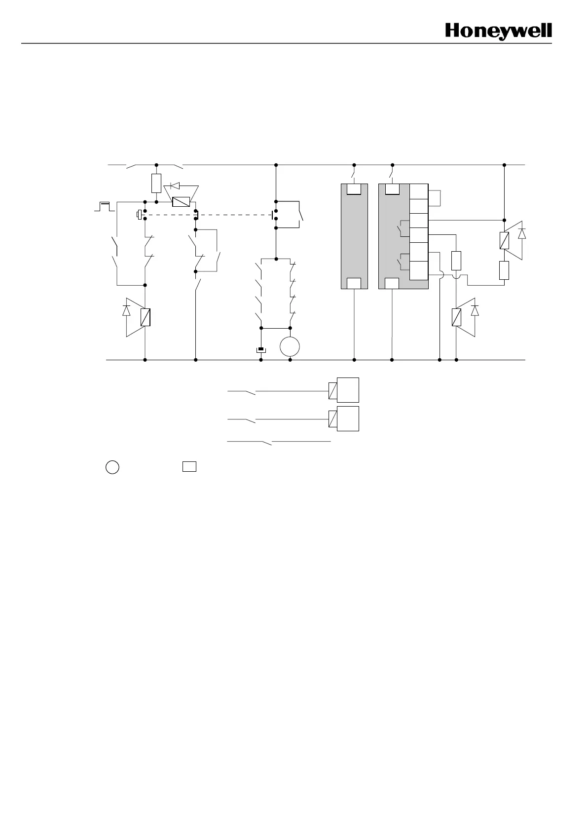
Example 7: The following example performs the same functions as the previous example but it takes
into account the secondary Switching Device.
This interface drawing meets the requirements of the BS 6491 standard.
: supply plug : signal plug
3
3
+
Power main switch
Power ON
K1
0V
K1
K2
Machine Control
K5
key op.
SSD
K6
K5
K5
SSD
Machine Power supply
K2
K5
K6
F
FF-SB
*
Receiver
F
F
K1
K2
K1
K2
K1
K2
SSD
MPCE1
MPCE2
MPCE1
MPCE2
MPCE
MPCE
FF-SB
Emitter
K6
SSD
K6
B2
B1
C1
C2
K6
FSD
FSD
SSD
FSD: Final Switching Device
SSD: Secondary Switching Device
MPCE: Machine Primary Control Element
C5
C4
A4A4
A5 A5
*the FF-SB receiver unit should be preset in the Automatic reset mode without FSD monitoring (refer to
§ 4.3 and § 8.6)
FSB14_50
 Loading...