26 107026-11-EN FR26 ROW 302 Printed in France
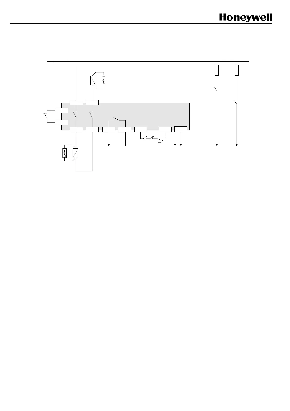
Example 6: Start/Restart interlock with Final Switching Device monitoring
(use of example 7 is recommended)
C1 B1
B2C2
C4
B3
Test
Machine stopping
circuitry
C3 C5
K2K1
Start P/B (NO)
A3
FF-SB14
Signalling
(beam status)
Signalling
(relay status)
K2
FSD
K1
FSD
FSD: Final Switching Device * 220 Ω + 0.22 µF
Do not forget to change the jumper links position (refer to § 8.6)
A2A1
K1
K2
*
*
In this example, it is necessary to press a NO push -button between C3 and C5 to reset the safety barrier at power up
and after any intrusion in the detection field. If one of the 2 additional relays K1 and K2 fails, reset is forbidden until
the failure is removed. Connecting NC contacts of K1 and K2 in serial with NO push-button between terminal C3 and
C5 will provide a fault-tolerant connection to the machine stopping circuitry.
All external relays are safety relays
with guided contacts.
FSB14_49
 Loading...