107026-11-EN FR26 ROW 302 Printed in France 39
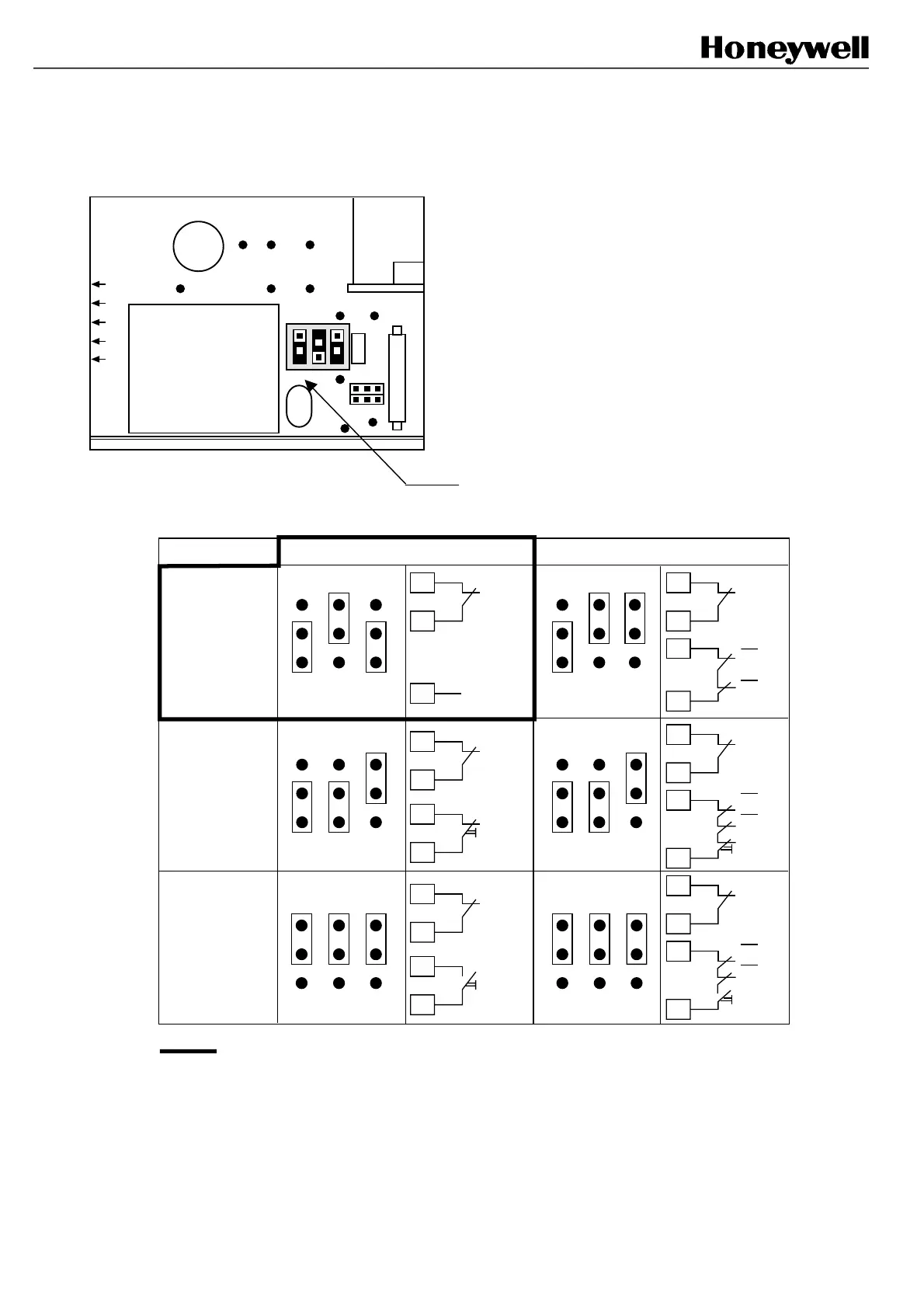
8.6 Changing the jumper links position (for models with DIN 43652
connectors only)
Flat cable
Relay
Fuse
R
C
Transformer
Connector side
Jumper links position and external connections:
Re-start mode Without FSD monitoring
With FSD monitoring
Automatic
Start
Interlock
Start
& Restart
Interlock
C3
NC P/B
: mode of delivery
NC
C4
C5
TEST
C4
B3
TEST
C5
C3
K1
K2
C4
B3
TEST
C5
C3
C4
B3
TEST
C5
C3
K1
K2
NC P/B
NO P/B
C4
B3
TEST
C5
C3
C4
B3
TEST
C5
C3
K1
K2
NO P/B
Notes:
- In many mode different than the “Automatic without FSD monitoring” mode, terminal B3 must be used for the test
input. It will forbid correct operation of a barrier accidentaly set in the “Automatic without FSD monitoring mode”.
- If the mode of delivery is kept for the application, then terminal C5 shall be used for the test input, and this barrier
remains compatible with former models (and can be used on installations made before November 95).
Follow the steps 8.3.a to 8.3.b till the jumper links (1)
are exposed (8.6.1). Then change the jumper links
position as follows:
(1)
Fig. 8-3-2
FSB14_64
 Loading...