107026-11-EN FR26 ROW 302 Printed in France 3
3. Installation
3.1 Statutory mounting provisions
The installation of the barrier has to be carried out in
such a way that access to dangerous moving parts is
impossible without breaking the beams.
This is determined by the distance between the barrier
and the dangerous parts in accordance with the following
formula:
S ≥
≥≥
≥ K (t1 + t2) + C
Where:
• S = distance (in mm)
• K = penetration velocity (in mm/ms)
• t1 = response time of the safety barrier (in ms)
• t2 = stopping time of the machine (in ms)
• C = guarded space for a barrier with 35 mm
sensitivity.
Values of parameters:
• Response time of the FF-SB14 barrier (t1 in ms):
Nominal Height
(in mm)
400 600 800 1000 1200 1400
Response time
(in ms)
non filtered
25 26 27 28 29 30
Response time
(in ms) filtered
40 41 42 43 44 45
• Values of K and C according to the EN 999
("Safety of machinery - The positioning of protective
equipment in respect of approach speeds of parts of the
human body") European project norm:
The approach speed "K" depends on the position of the
barrier and the guarding space "C" depends on the
resolution of the barrier, “C” being 168.
According to the EN 999 norm, the 35 mm resolution of
the FF-SB14 barrier is suitable for hand detection, when
the barrier is not used for the initiation of the machine.
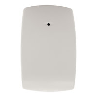
Normal approach:
The safety distance "S" allowed from the danger zone
to the vertical detection plane should be no less than
that calculated using the following formula:
S ≥
≥≥
≥ 2 x (t1 + t2) + 168
This formula applies for all safety distances of "S"
greater than 100 mm up to and including 500 mm.
If "S" is found to be greater than 500 mm using the
above-mentioned formula, then the distance may be
reduced using the following formula with a minimum
distance of 500 mm:
S ≥
≥≥
≥ 1.6 (t1 + t2) + 168
Then in any case ”S” should be greater or equal to
500 mm. When access to the danger zone can be gained
over the top or underneath of the barrier, additional
safeguarding devices should be provided to prevent
access.
S
Moving
part
Tool
Ground
level
45˚
S1
Normal
approach
Protected zone
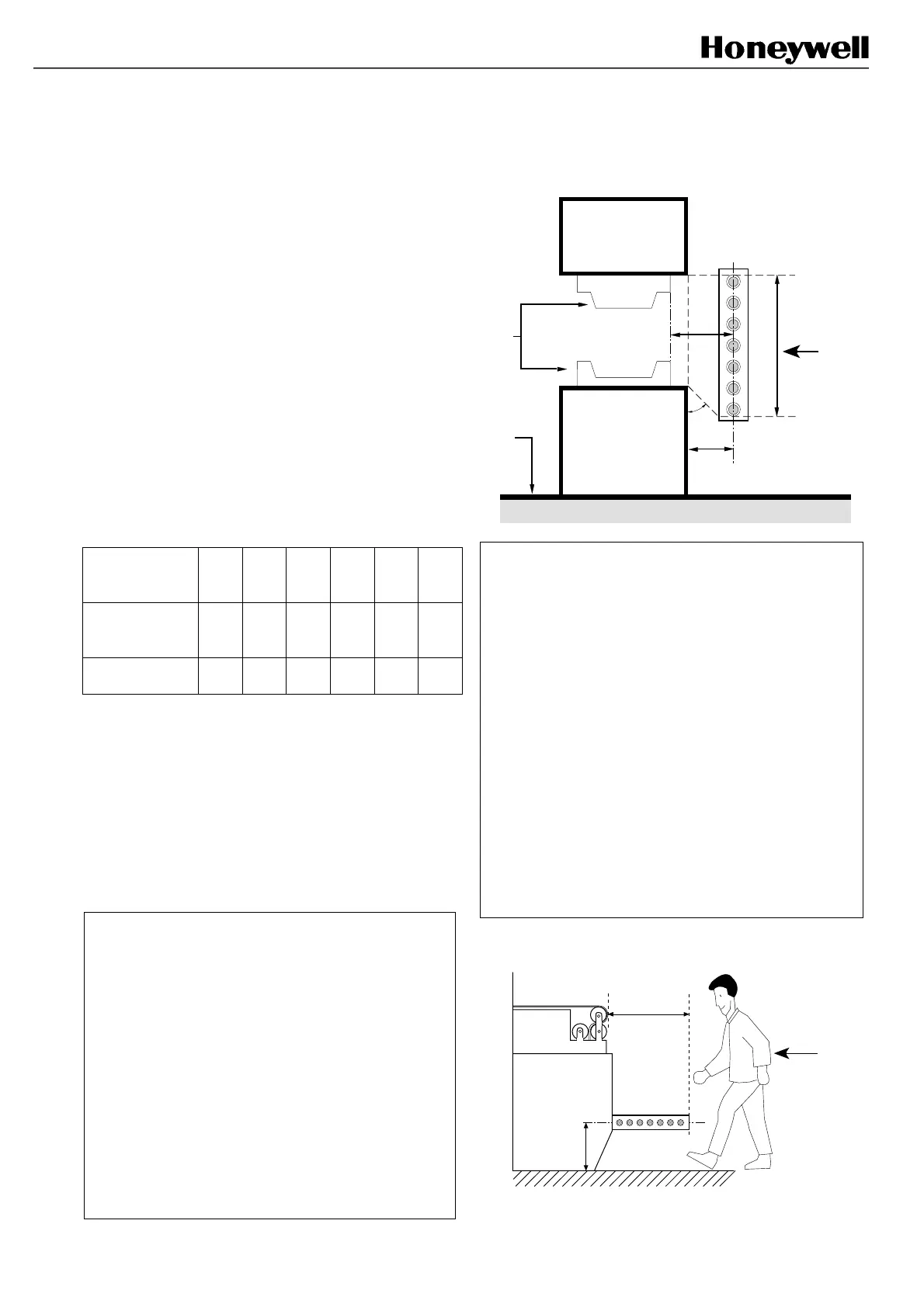
Parallel approach:
If the direction of approach is parallel to the plane of
detection, e.g. if the barrier is horizontally mounted, the
minimum safety distance "S" from the danger zone to the
outer beam depends on the height "H" of the curtain
above the ground. This safety distance "S" should be
calculated using the following formula:
S ≥
≥≥
≥ 1.6 (t1 + t2) + 850, 875 < H ≤
≤≤
≤ 1000
Or
S ≥
≥≥
≥ 1.6 (t1 + t2) + (1200 - 0.4 H), 0 < H ≤
≤≤
≤ 875
The height "H" should be a maximum of 1000 mm from
the ground. However, if the installation height "H" is
greater than 300 mm, there is a risk of inadvertent
undetected access beneath the curtain, and additional
safety measures are required (see note 1).
Example: if H = 300 mm then S ≤ 1.6 (t1 + t2) + 1080.
S
H
Parallel
approach
FSB14 3
FSB14 4
 Loading...