107026-11-EN FR26 ROW 302 Printed in France 19
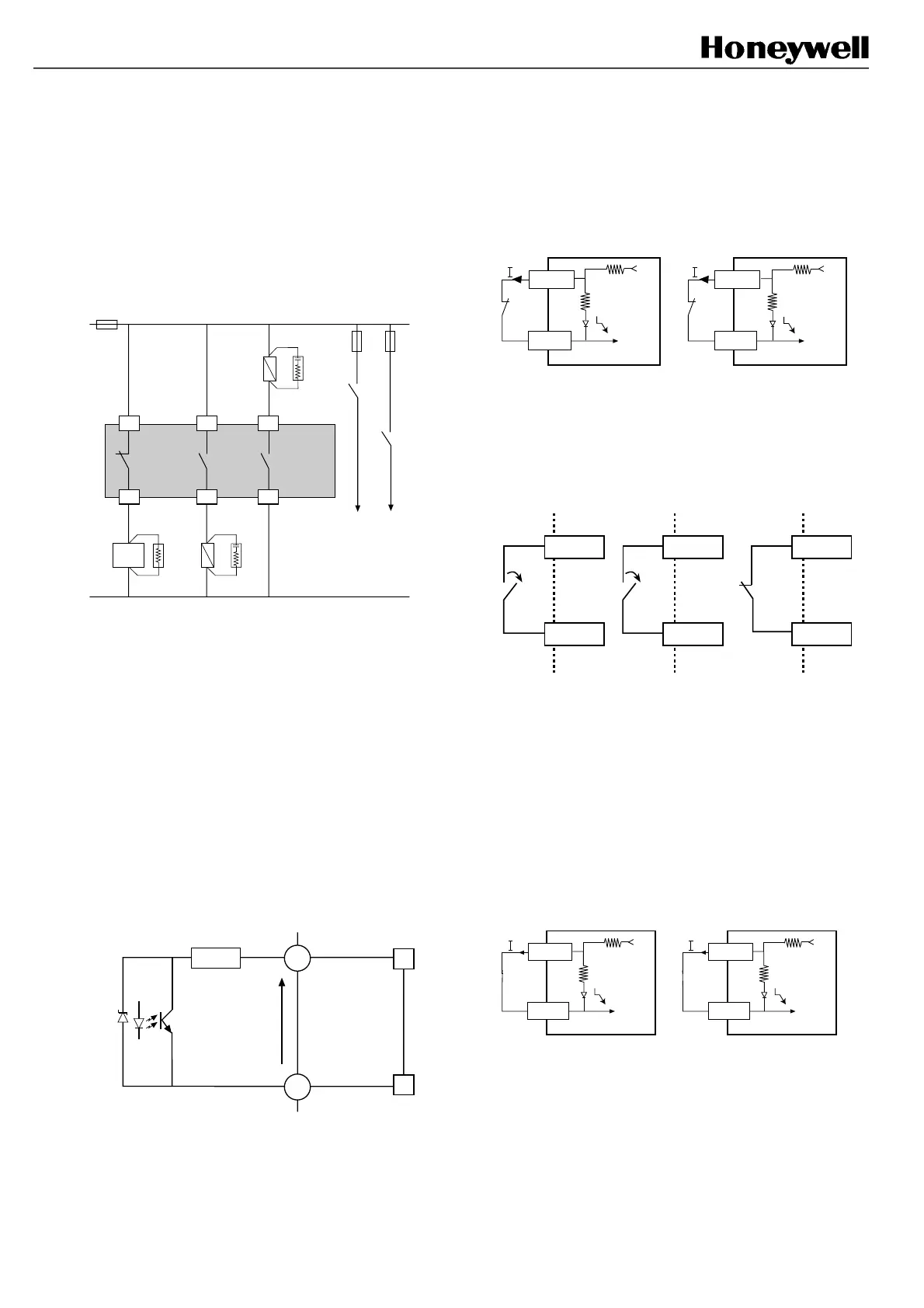
4.3.5 Use of auxillary N.C. contact
(pins A1 and A2)
Never use this contact alone for machine
shutdown.
These contacts can be used:
- either for indication of the stop signal from the barrier
- or as redundant complement to the main stop chain.
Machine
stopping
circuitry
K2
FF-SB14R
*
C1
K1
C2A2
A1
B2
K2
B1
PLC
K1
Auxiliary
contact
*Additive resistor to increase the current up to 50 mA
at least. PLC: Programable Logical Controller. The
partial example here being more appropriate for ac
power. See § 4.3.10 for correct interfacing of K1 and
K2.
4.3.6 Beam status output (available on
FF-SB14R❏❏❏
❏❏❏❏❏❏
❏❏❏-S2❏
❏❏
❏ models only)
A3 is internally connected to the 0 V when all the
beams are unobstructed (NPN output) and when the
light curtain is not in test mode. PLC: Programable
Logical Controller. The partial example here being
more appropriate for ac power. See § 4.3.10 for
correct interfacing of K1 and K2.
.
+
-
A3
C5
I ≤ 20 mA
100 Ω
0 V
V
OH
max
<30 V
PLC
39 V
V
OL
max
= 2,5 V
4.3.7 Test input
Principle
Interruption (by a contact Imax ≥ 20 mA, voltage drop
≤ 0,4 V) of the electrical connection between following
terminals of the receiver plug sets off the barrier even
if the beams have not been broken.
C4
C5
0 V
Receiver
plug
Automatic mode without
FSD monitoring
C4
B3
0 V
Receiver
plug
Other modes
+
+
The barrier only functions when connection between
these terminals has been made.
Interruption of the connection between these terminals
causes: the opening of the machine stop contacts and
the closing of the auxiliary contacts:
B2 C2
B1 C1
FF-SB14R
- receiver plug
A1
A2
Once connection between C4/C5 or C4/B3 has been
broken (tmini = 50 mS), it is enough to check that the
relays, controlled directly by the outputs of the
FF-SB14, have switched satisfactorily.
Warning: if the test function is not being used, then
do not forget to make the connection between
following terminals in the receiver plug:
C4
C5
0 V
Receiver
plug
Automatic mode without
FSD monitoring
C4
B3
0 V
Receiver
plug
Other modes
+ +
FSB14_35
FSB14_36
FSB14_37
FSB14_38
FSB14_39
 Loading...