34 107026-11-EN FR26 ROW 302 Printed in France
• Emitter
E2E1
• Receiver
FSB14_51
FSB14_52
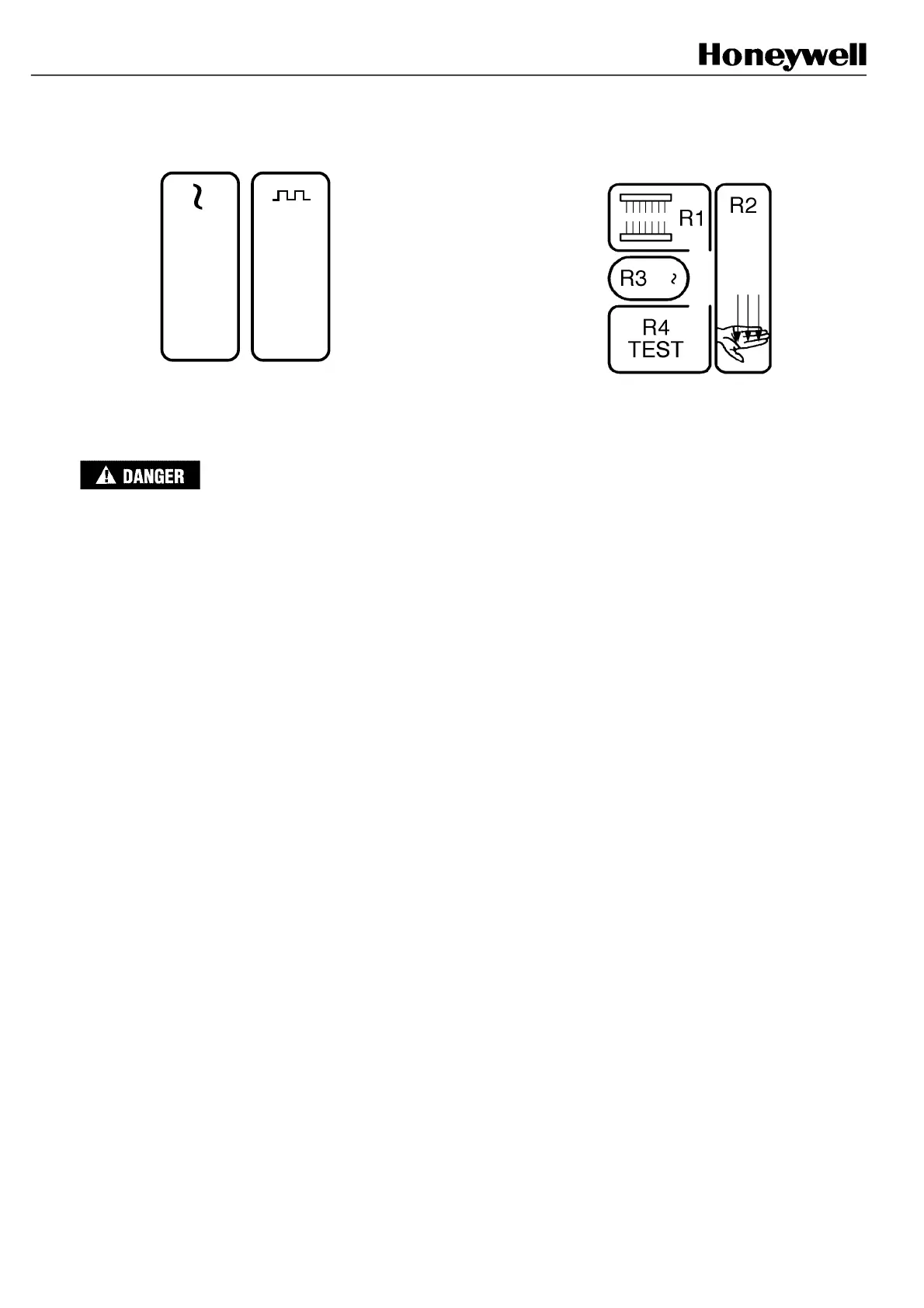
Supply voltage
Synchronization beam
Cleared field
Broken field
Signal margin
IMPROPER RELAY OUTPUT BOARD MAINTENANCE
• After a period of extended operation, it is possible that a switching relay can malfunction such that it remains
stuck of fused in the closed position following a breach of the light curtain’s protection field and the shutdown
of the machine.
• In the case of such a relay malfunction, the machine will not restart following the clearing of the protection field
(and pressing of the restart button when in manual restart mode) and the following warning diagnostic LED
condition will be seen on the light curtain receiver unit:
• R2 (red) ON R1 (red) OFF R4 (yellow) FLASHING R3: OFF
• It is essential to immediately replace the relay board upon the first occurrence of a stuck or fused relay and the
activation of the receiver operation status LED R2.
Failure to comply with these instructions could result in death or serious injury.
 Loading...